Design parts, sheet metal and assemblies.
Isovio Design is the CAD in Isovio: parametric, with sketches, features and assemblies. Because the program knows threads, fits and sheet thickness from the feature, the drawing is created with one click and stays linked to the part. Includes the drawing editor.
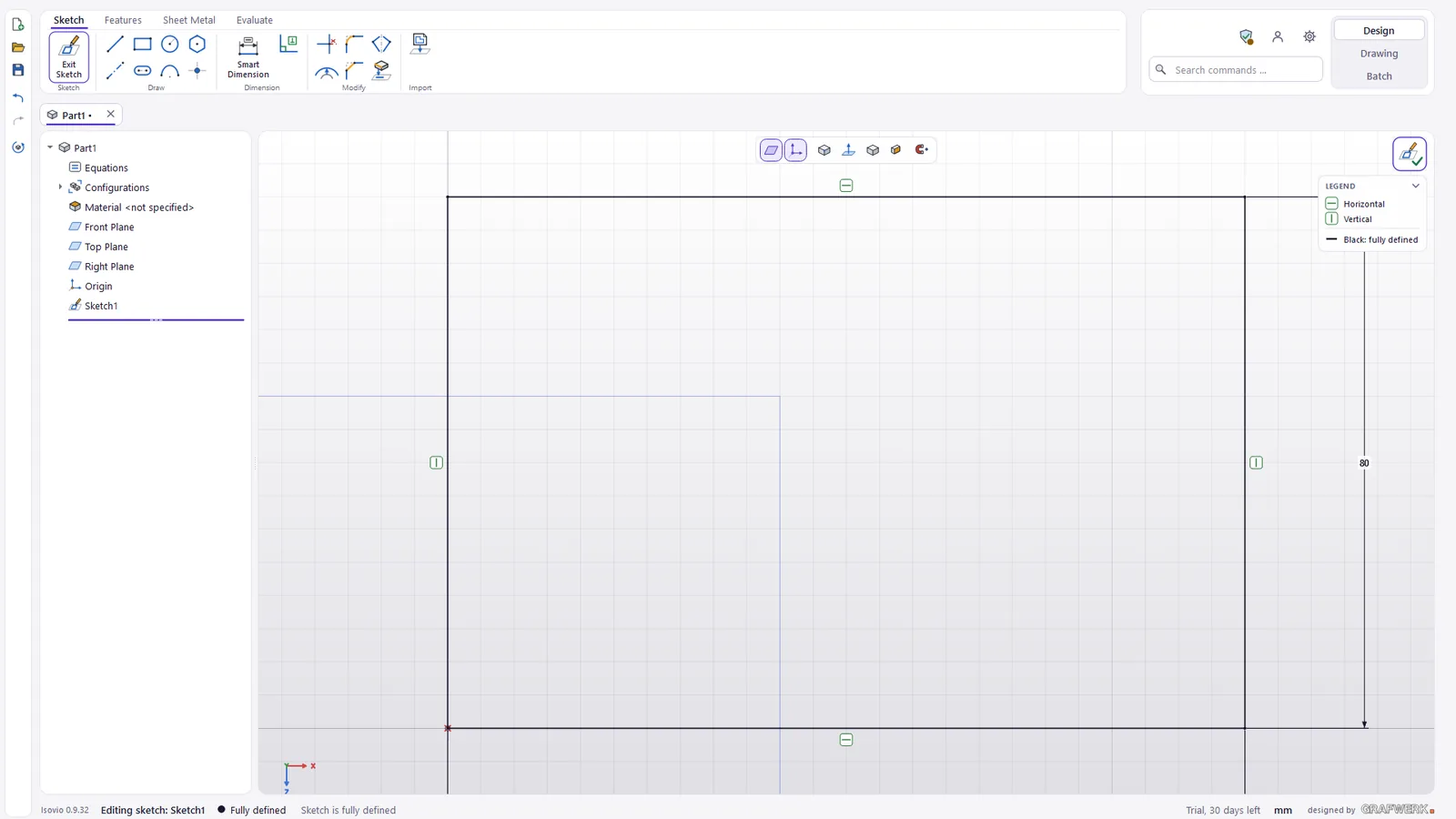
Sketches with constraints and smart dimensions
Every part starts with a sketch. Constraints hold the geometry together, dimensions go straight onto the contour. Equations and parameters make dimensions depend on each other, and a DXF file can be taken over as a sketch.
- Constraints keep lines, arcs and distances in place
- Equations and parameters change one dimension, the dependent ones follow
- DXF import bring existing 2D contours into the sketch
- Reference planes and axes for sketches that do not sit on a face
Features for milled and turned parts
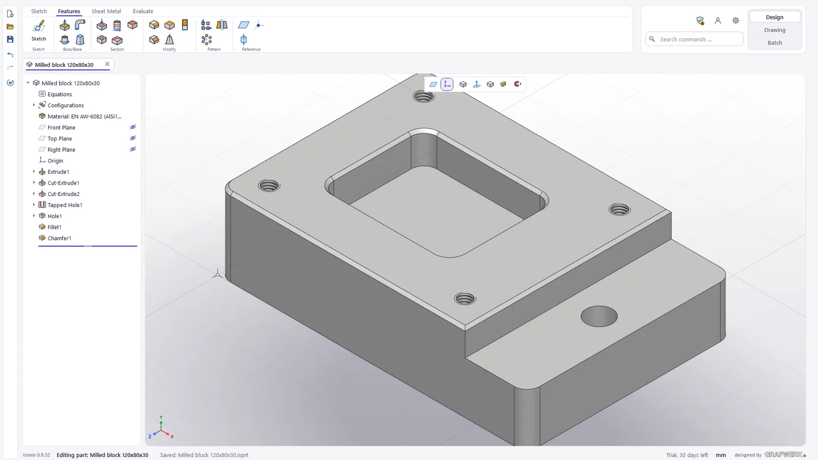
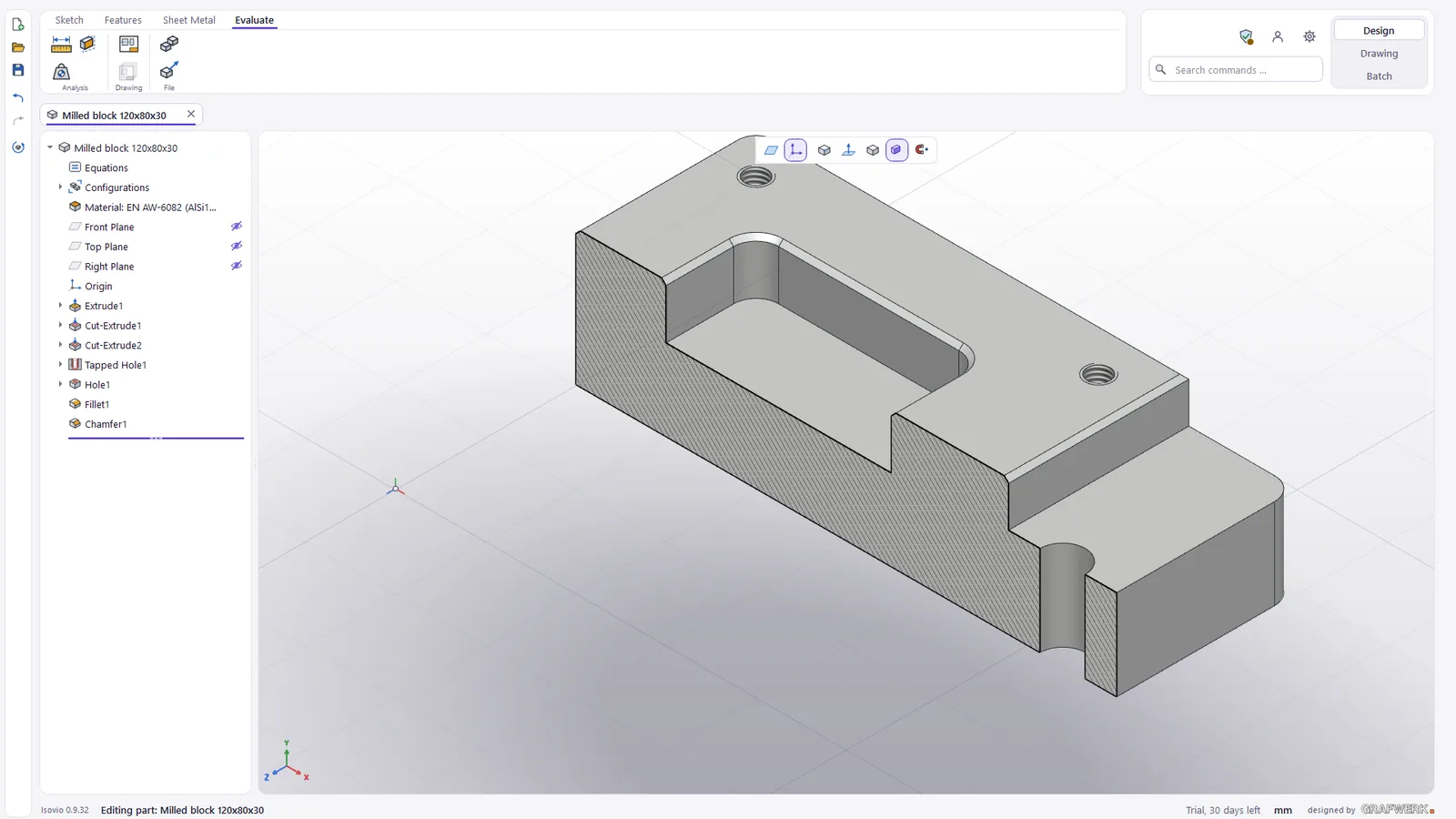
Extrude, revolve and cut give the part its shape; fillet, chamfer, shell, pattern and mirror work it out. For free forms there are sweep and loft, for castings the draft.
- Material and mass stored with the part
- Feature tree every step stays editable
Hole wizard with standards
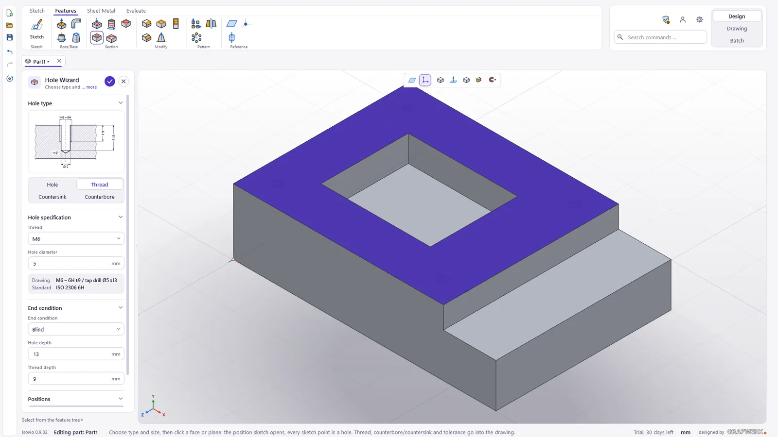
You do not place holes as cylinders but as holes: the wizard knows the standard sizes. That way the drawing knows what is a thread and what is a countersink.
- Clearance holes to ISO 273
- Threads with the matching tap drill
- Counterbores and countersinks to DIN 974-1 and ISO 15065
Sheet metal: from flange to flat pattern
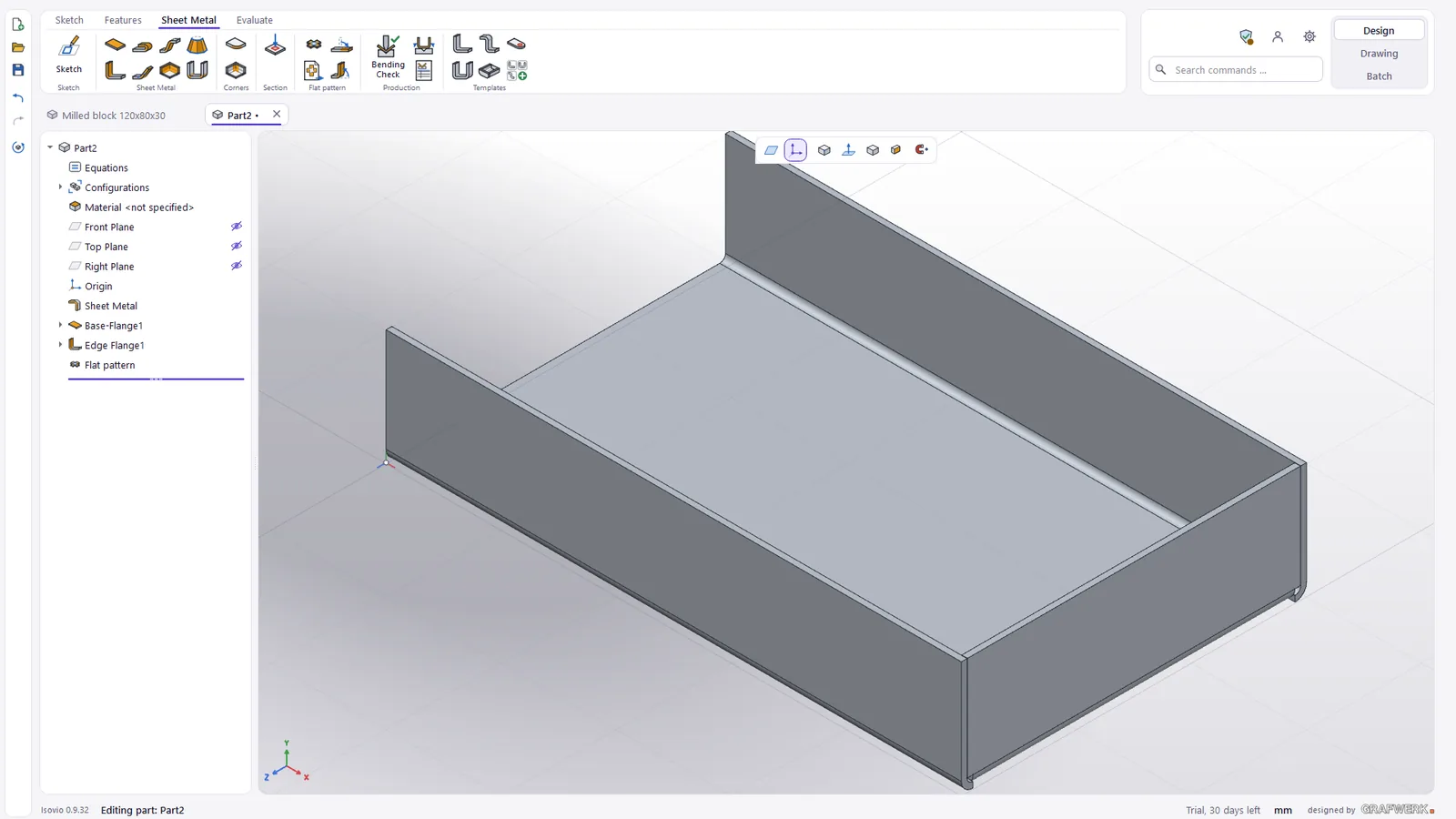
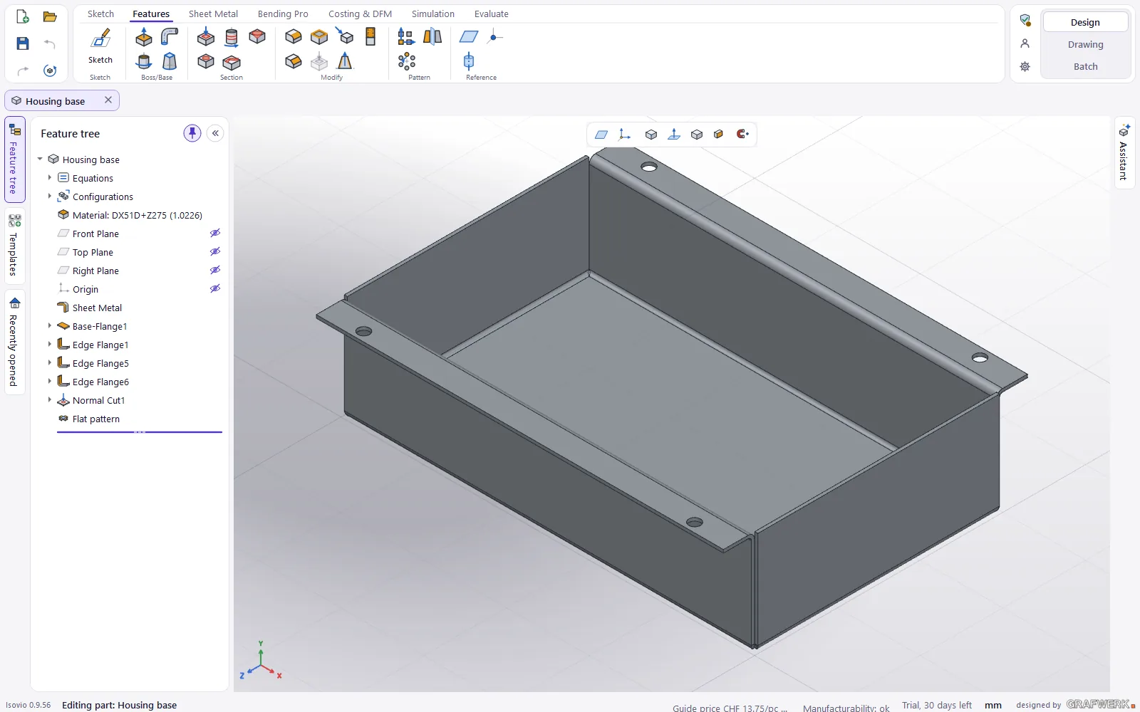
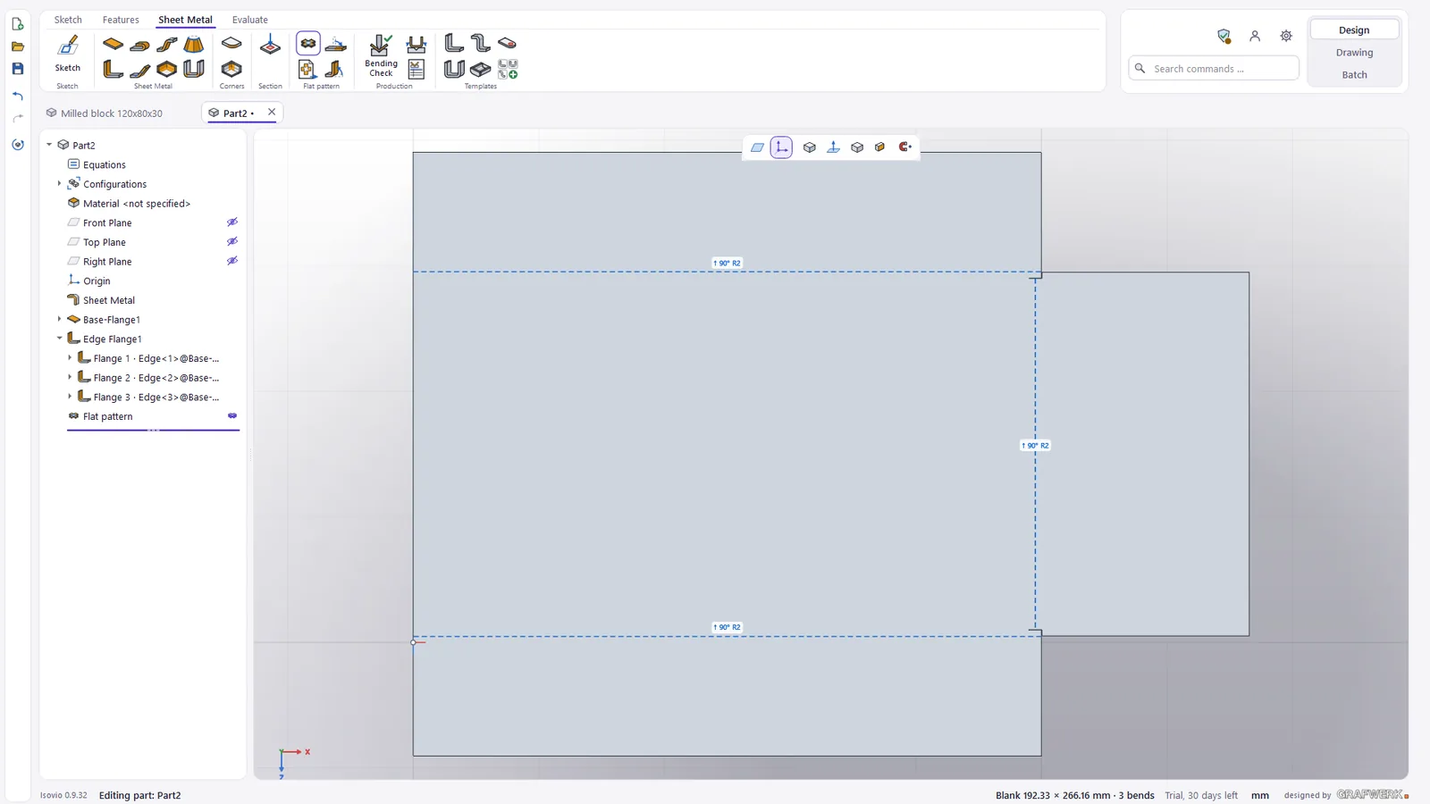
Draw a base flange, add edge flanges with their own profile, hem, jog, sketched bend and miter flange, close or break corners. Templates cover the common shapes.
- Templates angle, U, Z, box and tab
- Flat pattern as DXF for cutting
- Slot-in joints tab and slot and cross slot joints between sheet metal parts, new, no surcharge
- Drawing with flat pattern and bend table
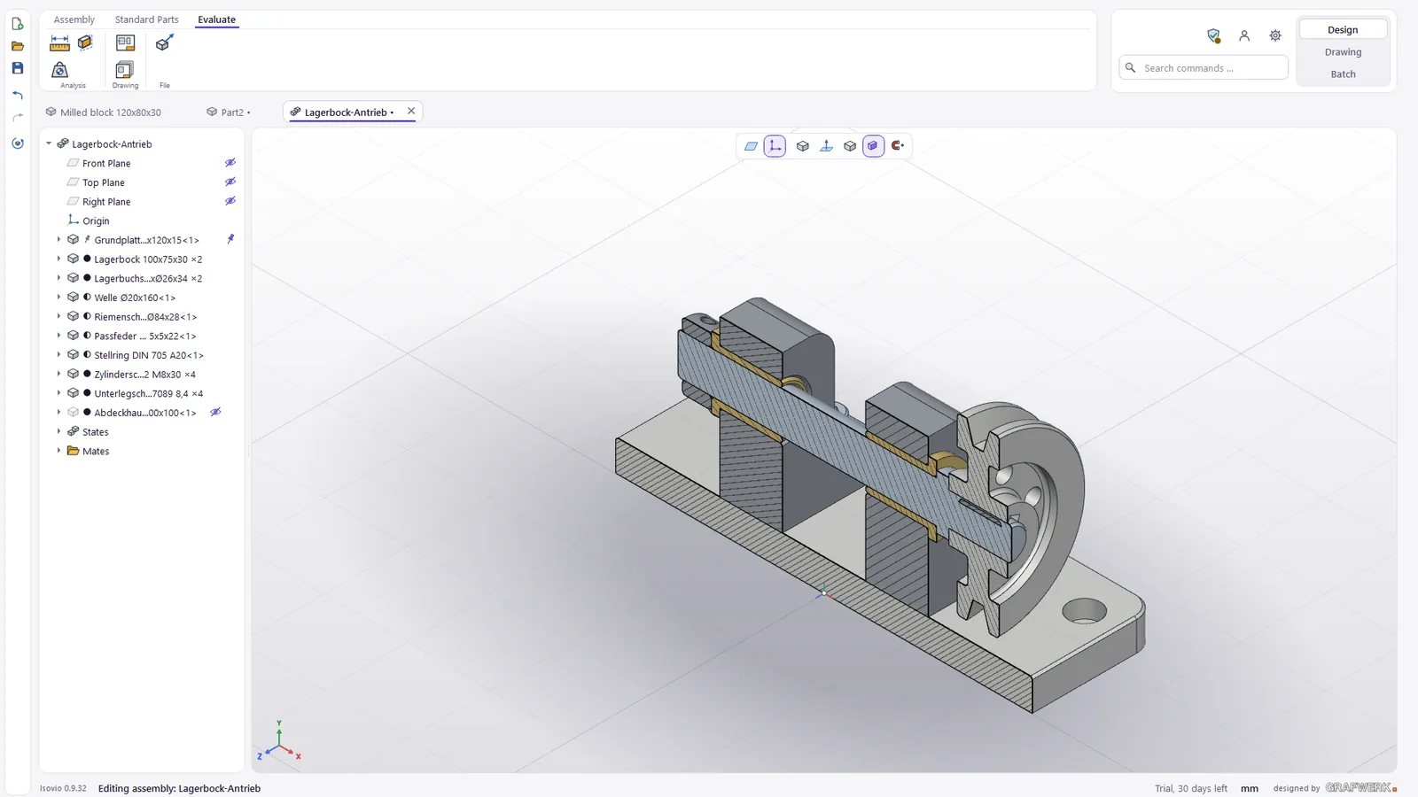
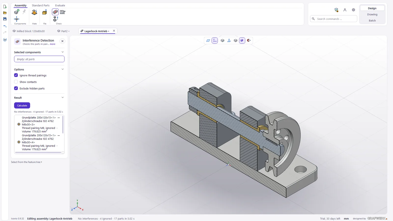
Assemblies with mates
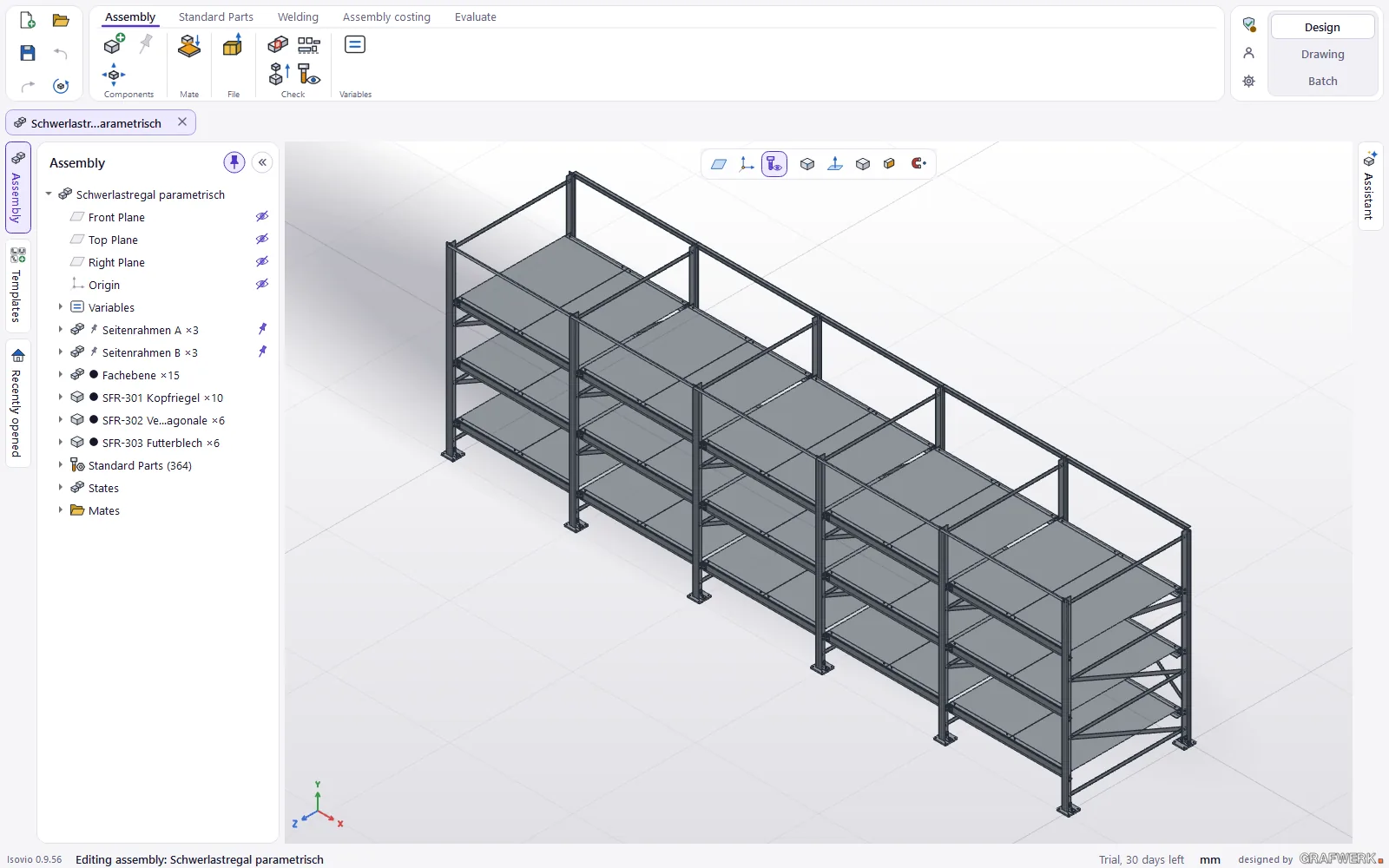
You drag components into the assembly with the mouse and mate them. Then they can be moved and rotated live, as far as the mates allow. Sub-assemblies stay flexible if you want.
- Hide standard parts screws, nuts and washers out of the 3D view in one click, the parts list still counts them
- Assembly video the assembly or the build of a part as an MP4 time-lapse
- Pack and Go the assembly with all its parts into one folder
- Draw single parts every part of the assembly as an Isovio drawing
- Assembly drawing straight from the assembly
Open STEP and keep building
Isovio recognises sheet metal parts from STEP and rebuilds them as base flange with edge flanges; milled and turned parts get recognised features. Broken STEP files can be repaired.
Extensions to Design
Automatic (drawings), Welded assemblies, Tube & Profile, Metal construction, Strength check and force flow and AI assistant: all extensions.
3D export
STEP, IGES, BREP, STL, 3MF, OBJ, GLB and VRML: for the customer, the supplier, 3D printing or the website.
The drawing
«Create drawing» turns part or assembly into the sheet. You finish it in the Drawing area.
What Design & Draw includes
The drawing editor, the parametric CAD with sheet metal and assemblies and Bending Basic: bend check, bend sequence by hand, setup sheet, tool and machine menu, pre-bend by hand, plus the manufacturability check (DFM). Extensions exist only with Design & Draw.