Isovio step by step.
From the first start to the finished workshop drawing: how to design, draw and use the automatic mode in Isovio, with pictures from the program.Version: Isovio 0.9.32
Getting started
Isovio has three work areas: Design for modelling, Drawing with the editor, and Batch for STEP models from other programs. You switch between them at the top right.
First start
Isovio always opens in the Design area and shows the layer «Welcome to Isovio» at the start. Sign in with the e-mail address and password of your Isovio account. With «Save password» switched on, Isovio no longer asks for it at the next start.
Without a licence, choose «Continue with the trial»: 30 days from the first start, the whole program with Design, Drawing and Batch. During this time drawings and exports carry the watermark «Trial version».
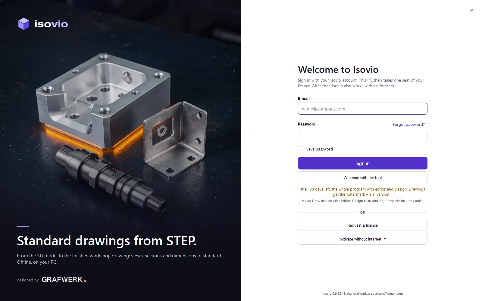
For PCs without internet there is «Activate without internet ▾»: «Save request …» saves a file that you send us by e-mail. Load the licence file you receive with «Load licence file …» or drag it into the window.
Tip Without a licence and after the trial, the free viewer remains: open, view and print Isovio drawings (.fdw), Isovio PDFs and Design parts.
The window
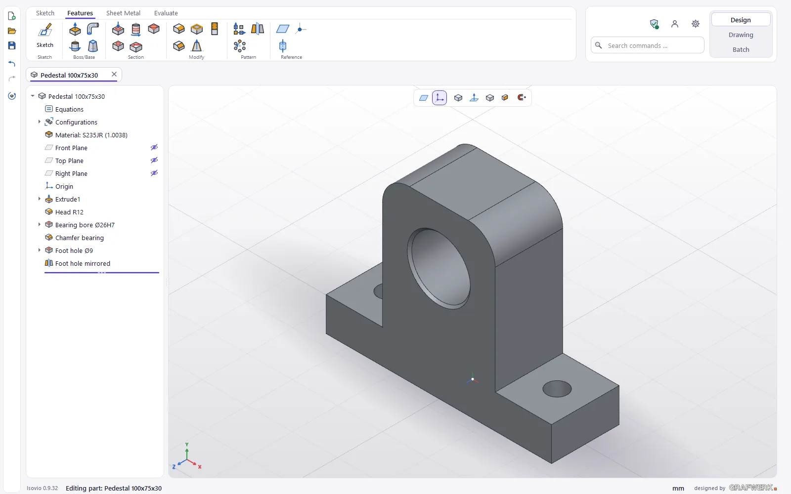
With a document open, the ribbon sits at the top in the head of the window. Every tab has sections with two rows of icons and the name of the section below them. The tooltip shows the name of a command and its shortcut; what does not fit the moment is grey.
- At the right of the head: the licence status (a click shows the overview with «Check now»), «Account & licence», the gear «Settings» and below them the command search. Beside them the switch «Design | Drawing | Batch».
- At the left edge: the slim quick access bar with the menu «New», Open, Save, Undo, Repeat and Rebuild.
- On the left the tree, in Design the feature tree. In the middle the 3D view with the view bar: planes and origin on/off, standard views, «Normal To», «Display style», «Section view» and the magnet «Snap».
- At the bottom the status line: version, licence, hints for the running command and the unit (e.g. «mm»).
The Design start page
With nothing open, Design shows its start page. Drag a part (.isprt), an assembly (.isasm) or a STEP file onto «Drag a model here», or choose «Open …», «New Part» or «New assembly». Below are the rows «Start from a template» and «Recently opened».
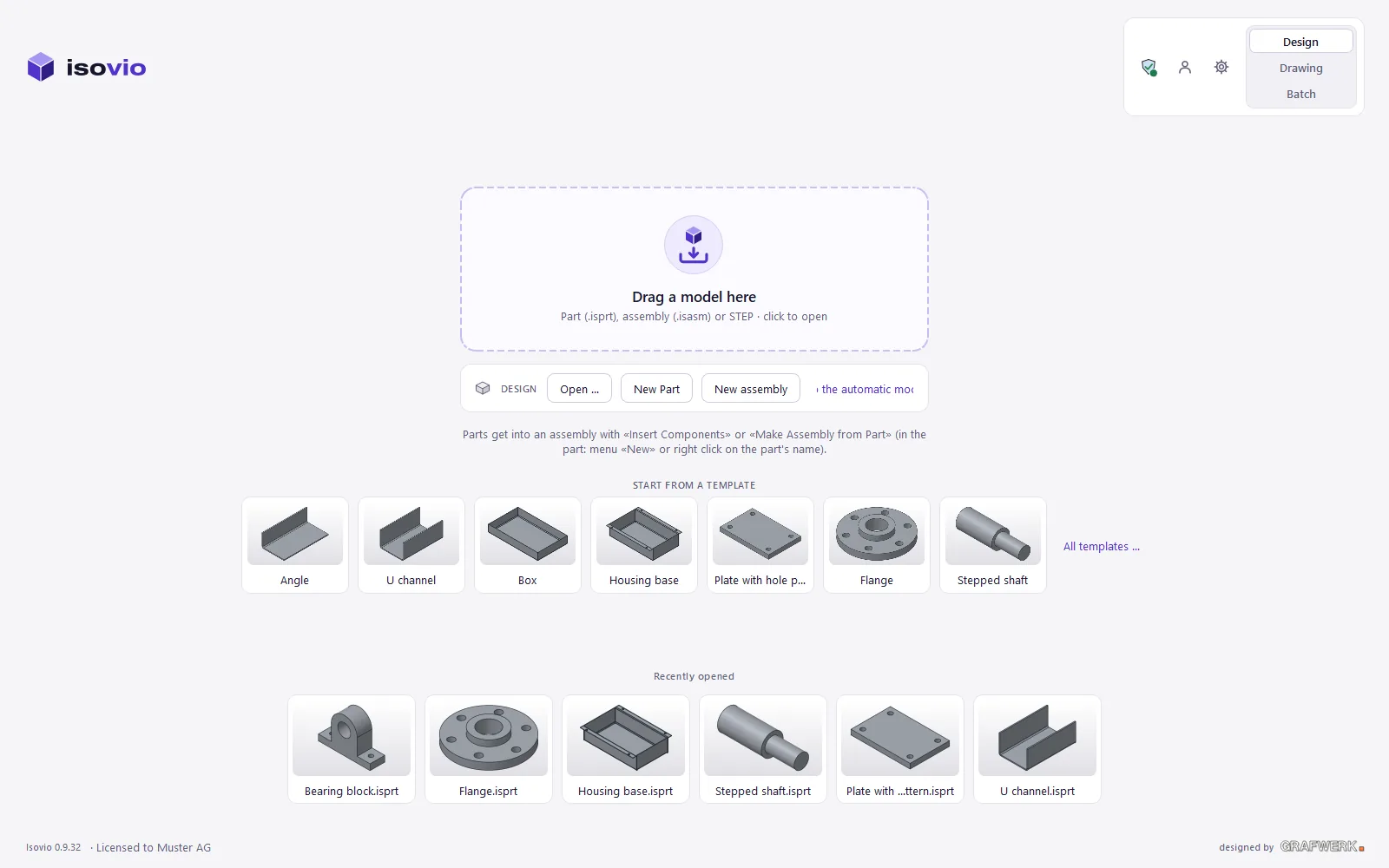
Tip A right click on a tile under «Recently opened» offers «Remove from the list» and «Open folder».
Command search and help
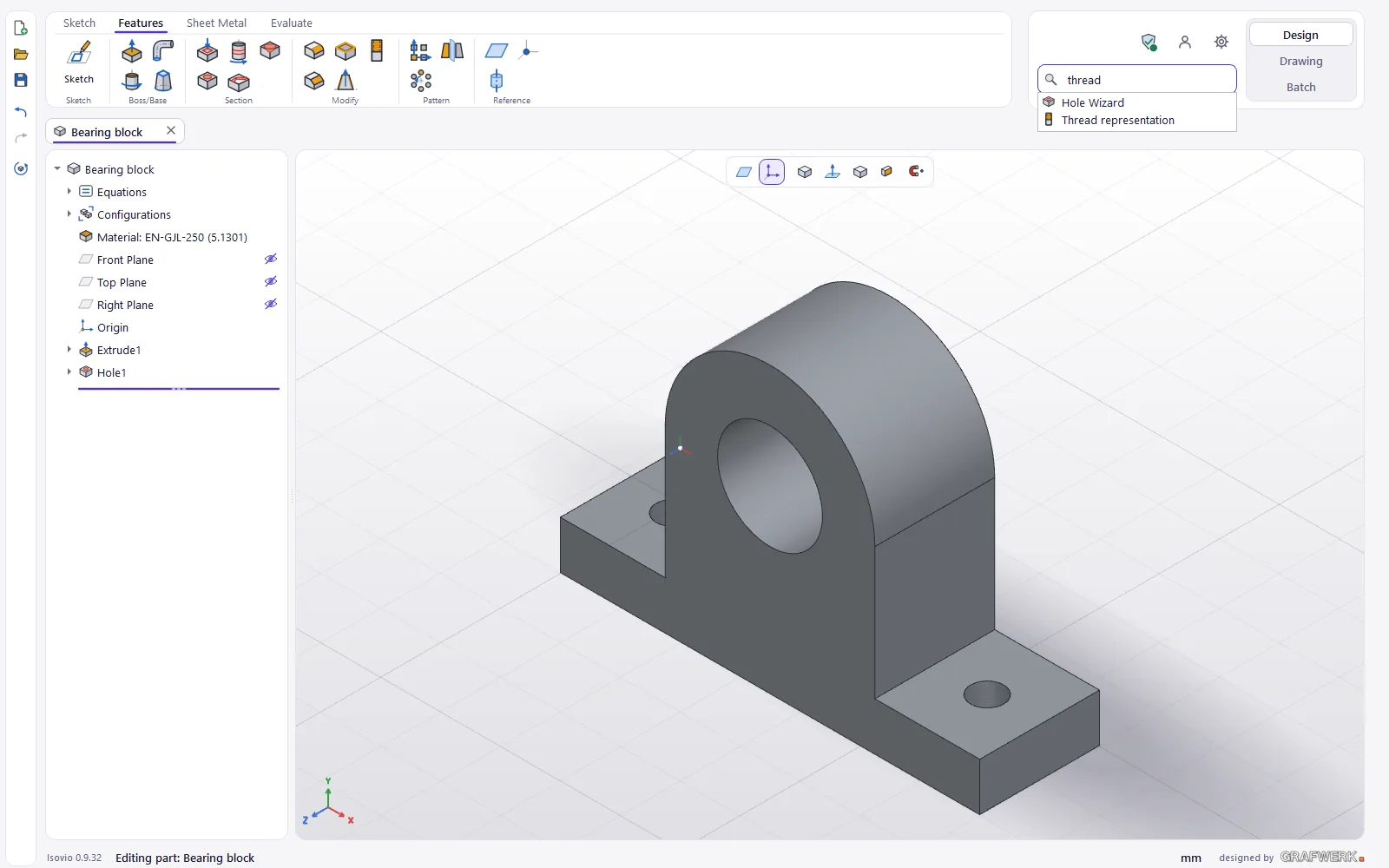
«Search commands …» finds commands by name and by keyword: «thread» finds the Hole Wizard. Enter starts the best match, Esc clears the field.
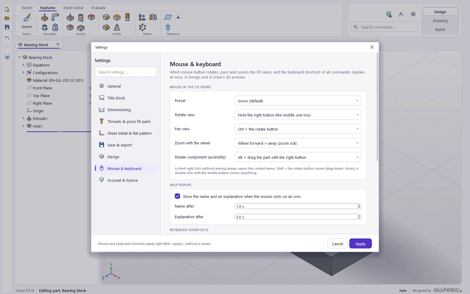
Point at an icon: after one second the name, the shortcut and a short sentence appear, after three seconds the explanation too. You set the times under Settings › «Mouse & keyboard» › «Help popups».
Files, colour scheme and language
| File | Contents |
|---|---|
| .isprt | Part from Design |
| .isasm | Assembly from Design |
| .fdw | Isovio drawing, editable |
| Isovio PDF | PDF with the drawing embedded; the editor opens it again |
| STEP (.stp, .step) | Models from other CAD systems, for Design, Drawing and Batch |
| DXF | Import into sketches and as a profile |
Design exports with «Export» (Evaluate › File) to STEP AP214, IGES, BREP, STL, 3MF, OBJ, glTF (.glb) and VRML. Drawings go out as PDF, DXF with layers, SVG and PNG at 300 dpi.
Choose the colour scheme (Light or Dark) and the language (Deutsch or English) under Settings › «General». A new language applies after a restart.
Design: modelling parts
In Design you model parts: draw and dimension a sketch, make features from it, drive dimensions with equations. Every step stays editable in the feature tree.
Starting a part
«New Part» (Ctrl+N) creates an empty part. It is quicker with a template or a profile from the library. A part has the tabs Sketch, Features, Sheet Metal and Evaluate and opens on «Features».
Drawing and dimensioning a sketch
- Select a plane or planar face and click «Sketch». Without a selection a panel asks for the plane. The view turns normal to it and the ribbon switches to the Sketch tab.
- Draw: line, rectangle, circle, arc, slot, polygon, point or centre line. A tool stays active until you press Esc. The line draws a chain click by click; a double click or Esc ends it, Shift snaps to 0°, 45° and 90°.
- «Smart Dimension»: click one element (length, Ø, R) or two (distance, angle), click the place and type the value, also as a formula such as «= Width / 2». A double click on a dimension changes it.
- Relations: select elements without a tool; a bar at the mouse pointer offers horizontal, vertical, parallel, perpendicular, tangent, concentric and more. H and V set horizontal and vertical directly.
- «Exit Sketch»: the button at the top right of the 3D view (sketch icon with a tick), the tile in the ribbon or the right click. If you start a feature while sketching, the sketch becomes its profile.
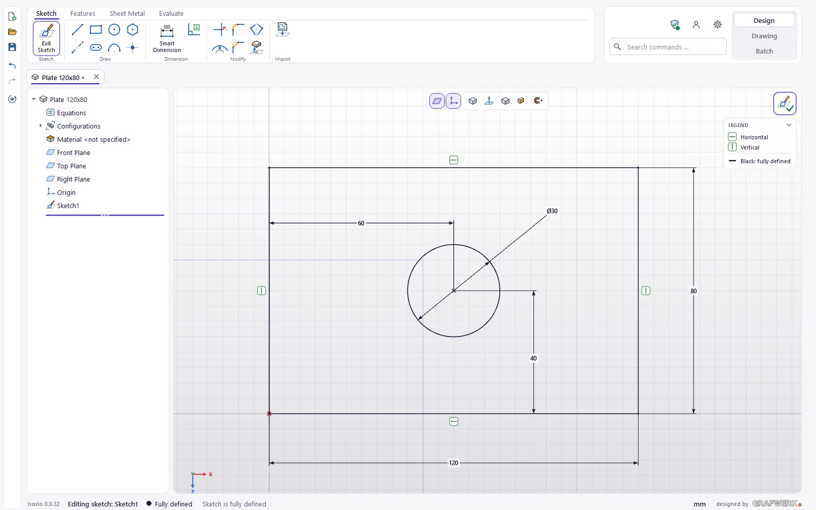
The colour shows the state: black is defined, blue under defined, red a conflict, grey dashed construction geometry and brown a model edge taken over. The «Legend» card explains the symbols, the status line names the state of the sketch.
Tip Bring a DXF contour into the sketch with «Insert DXF»: choose layers, unit, scale, reference point, position and rotation. The preview can be dragged and snaps to sketch points.
Features
The «Features» tab has the sections Boss/Base, Section, Modify, Pattern and Reference. Every command opens a panel on the left with ✓ and ✗ and shows the result live in the 3D view; every value field also takes formulas.
| Section | Commands |
|---|---|
| Boss/Base | Extruded Boss/Base, Revolved Boss/Base, Sweep, Loft |
| Section | Extruded Cut, Hole Wizard, Revolved Cut, Swept Cut, Lofted Cut |
| Modify | Fillet, Chamfer, Shell, Draft, Thread representation |
| Pattern | Linear Pattern, Circular Pattern, Mirror |
| Reference | Plane, Axis, Point |
- Select the sketch (or stay in the open sketch) and click «Extruded Boss/Base».
- Choose the end condition: Blind, Through All, Up To Surface or Mid Plane, and type the depth. The arrow in the 3D view drags the depth directly.
- Accept with ✓ or Enter, discard with ✗.
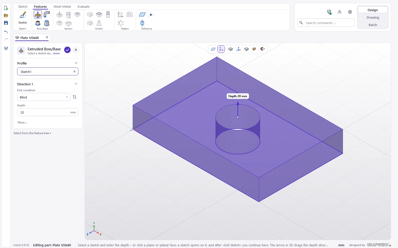
In the feature tree a double click opens a feature for editing. The right click offers Edit feature, Edit sketch, Suppress, Rename, Roll back to here, Up/Down and Delete. The rollback bar at the end of the tree can be dragged; Alt+↑ and Alt+↓ move a feature.
Tip A right click on an edge or face in 3D offers fillet, chamfer, Hole Wizard and measure directly.
Hole Wizard
The Hole Wizard places holes to the standards instead of plain cylinders. That way the drawing knows what is a thread, a counterbore or a fit.
- Choose «Hole Wizard» and set the type: Hole, Thread, Countersink or Counterbore. Choose the size; the panel shows the callout for the drawing and the standard.
- Click a face: the position sketch opens and every sketch point becomes a hole. Place the points and dimension them.
- «Exit Sketch»: back in the panel the preview shows the holes. Accept with ✓.
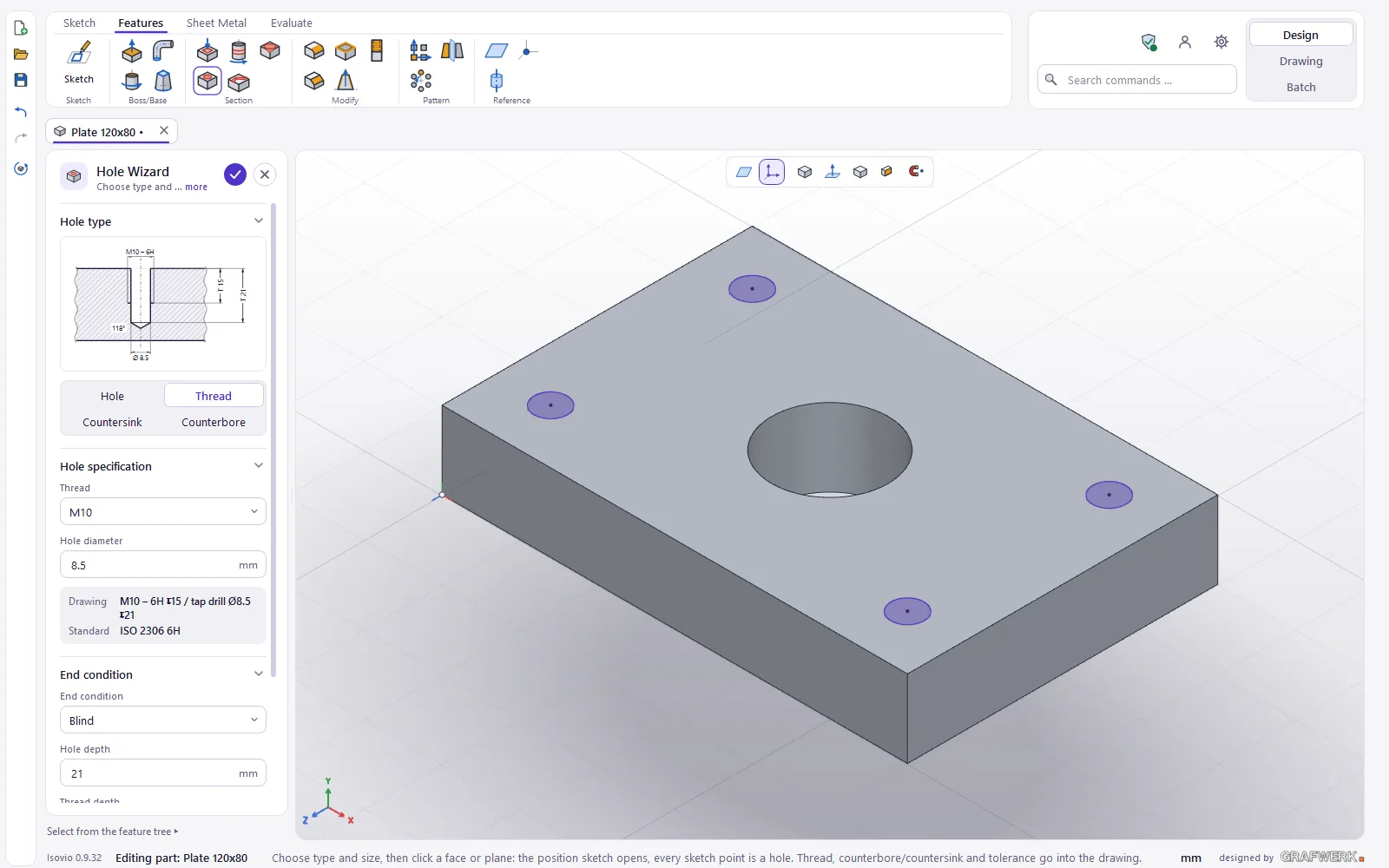
- Clearance holes to ISO 273 (fine, medium, coarse).
- Threads to ISO 261 with tolerance 6H, tap drill to ISO 2306 or DIN 336.
- Counterbores and countersinks to DIN 974-1, ISO 15065 and DIN 74, matching ISO 4762, DIN 7984, ISO 7380, ISO 10642, ISO 2009 and ISO 7046; or «Custom size».
- Tolerance: none, a fit to ISO 286 or deviations.
Change the position later with a right click on the hole › «Edit positions». «Thread representation» (Modify) marks a cylindrical face as a coarse or fine thread with tolerance 6g or 6H; the geometry stays smooth, the drawing shows the thread.
Equations, configurations, material
A double click on «Equations» in the feature tree opens the variables of the part. A variable has a value or a formula, such as «Width = 40» or «Depth = 2 * Width + 5», and can be used in every value field as «= Width». The model follows live while you type; ✓ is one undo step.
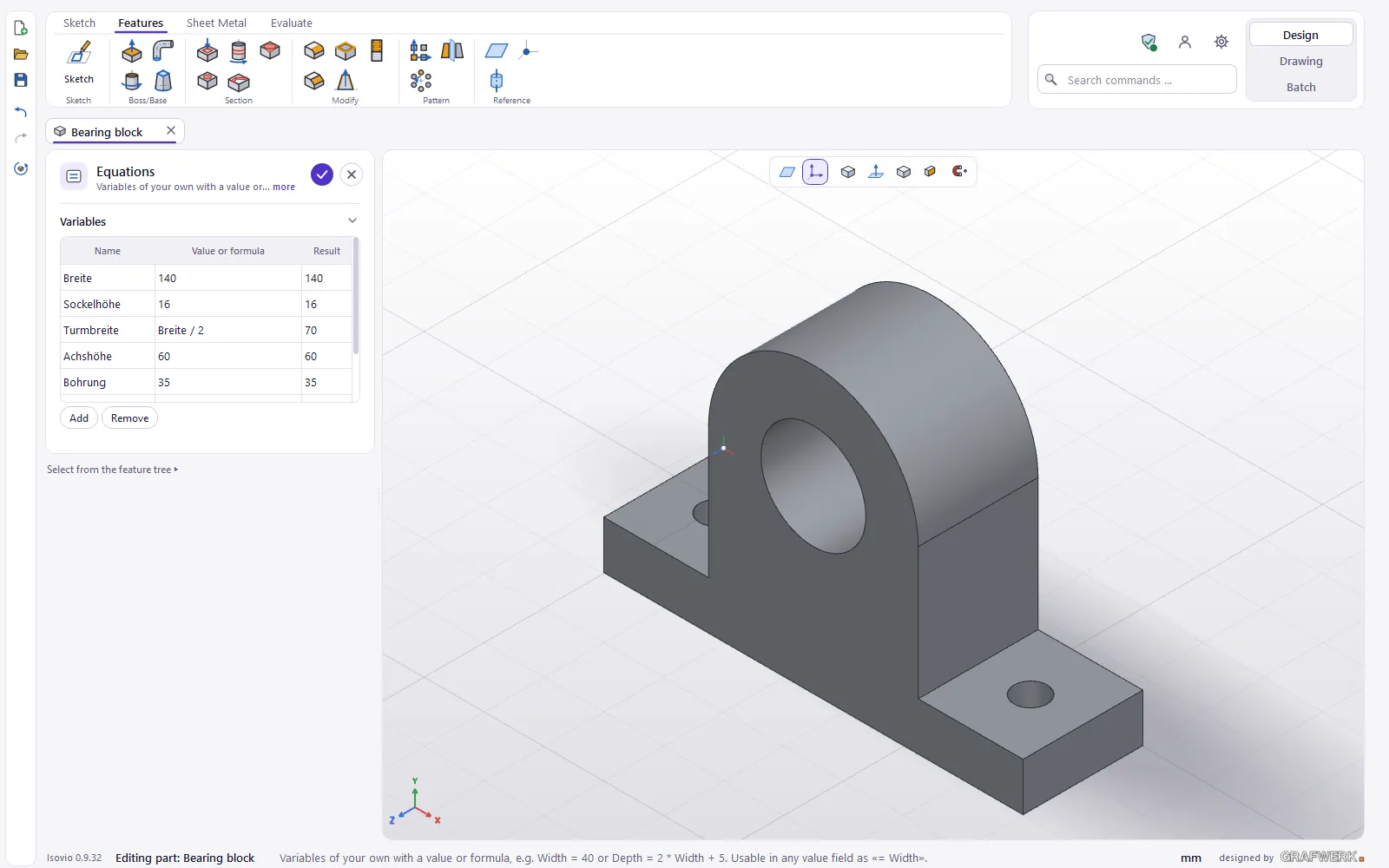
Create variants of a part under «Configurations»: «New configuration» or «Configuration table …» with one row per variant and one column per dimension («Add column …»). A double click activates a variant. The base is called «Standard», further ones -001, -002 and so on. On the drawing the variants appear as a table, with the weight of each.
Set the material with a right click on the tree row «Material: …» › «Edit material …». Material and weight go into the title block of the drawing.
Templates
Templates cover frequent parts: menu «New» › «Part from template …», the row «Start from a template» on the start page or Sheet Metal › «Templates». The gallery sorts them into sheet metal, milled and turned parts, profiles and your own templates.
- Choose the template in the gallery.
- Adjust the dimensions. The picture shows which dimension sits where; the field with the cursor lights up in the picture.
- «Create part» (or a double click on the tile): an ordinary part with named equations and material is created, then the «Equations» panel opens.
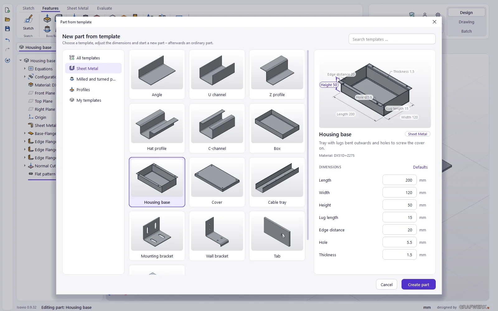
Your own templates: save a part with a body via the menu «Save» › «Save as template …». In the dialog you set name, category and description and choose the adjustable dimensions in the table «Variables» with name, default, min and max. In the gallery your own templates can be edited, renamed, exported as ZIP and deleted; «Import template …» brings a ZIP in.
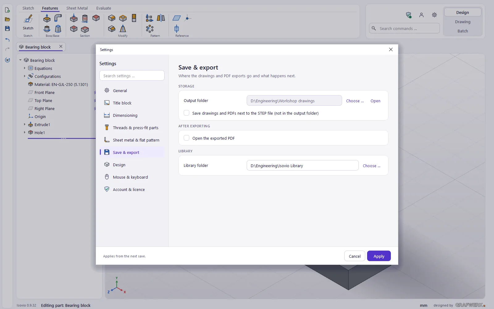
Tip Your own templates, profiles and bending tools are kept in the library folder, by default «Documents\Isovio Bibliothek». Choose another folder, for example on a network drive for the whole company, under Settings › «Save & export» › «Library folder».
Profiles
- Open menu «New» › «Profile from Library …» and choose a family: tubes, beams, angles and tees, cold formed sections, bars, system profiles or your own profiles. Method and standard filter the list.
- Enter the size under «Set dimensions» or click a common size in the «Quick pick», with cross section A and kg/m.
- Under «Length and ends» choose the length and the ends, straight or mitred, then «Create part».
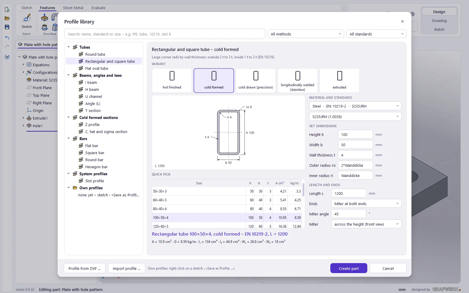
Your own sketch becomes a profile with a right click on the sketch in the tree › «Save as Profile …». Bring in a contour from a DXF file with «Profile from DXF …» (unit, origin, scale) and save it as a profile or use it only once.
Measuring, section and views
- Evaluate › Analysis: «Mass Properties», «Measure» (Ctrl+M, one or two elements) and «Section view» with up to three planes; drag the arrow, hatched or in part colour. The section is only a view and does not change the part.
- Views: Ctrl+1 to Ctrl+6 for front, back, left, right, top and bottom, Ctrl+I or Ctrl+7 isometric, Ctrl+8 normal to, F zooms to fit; the Space bar opens the view selector.
- Split view: drag a document tab into the 3D view or right click the tab › Split right, Split down, Unsplit.
- Units: the button in the status line (e.g. «mm») chooses the unit of lengths and the unit system. A value with a unit such as «1 in» works in every field, angles always in degrees. Inside, Isovio calculates in mm.
Sheet metal and bending
The «Sheet Metal» tab has the sections Sketch, Sheet Metal, Corners, Section, Flat pattern, Production and Templates. In the section Production you check whether and in which order the part can be bent on the press brake.
Creating a sheet metal part
«Base Flange/Tab» turns a closed contour into a flat plate of sheet thickness and an open profile into a profile with bends; on a sheet face it makes a tab. Drag the thickness at the dimension line in 3D; the material lies inside, outside or centred.
The first feature in the tree is called «Sheet Metal». Its pencil icon opens «Edit sheet metal parameters …»: thickness, bend radius (inside), material, relief, corner gap and corner relief. Isovio calculates the bend allowance automatically from the K-factor table under Settings › «Sheet metal & flat pattern», otherwise to DIN 6935, or with a fixed K-factor.
Tip It is quicker with a template from Sheet Metal › «Templates»: angle, U, Z, hat and C profile, box, housing base, cover, cable tray, mounting bracket, wall bracket, tab and flat sheet with hole pattern.
Edge flange
- Choose «Edge Flange», or right click a sheet metal edge.
- Click one or more edges and enter the angle.
- Under «Flange length» choose the reference (Outer virtual sharp, Inner virtual sharp or Virtual sharp) and type the length, or drag the dimension line in 3D at its end; a double click on the dimension line types the value.
- Under «Flange position» choose Material inside, Material outside or Bend outside and accept with ✓.
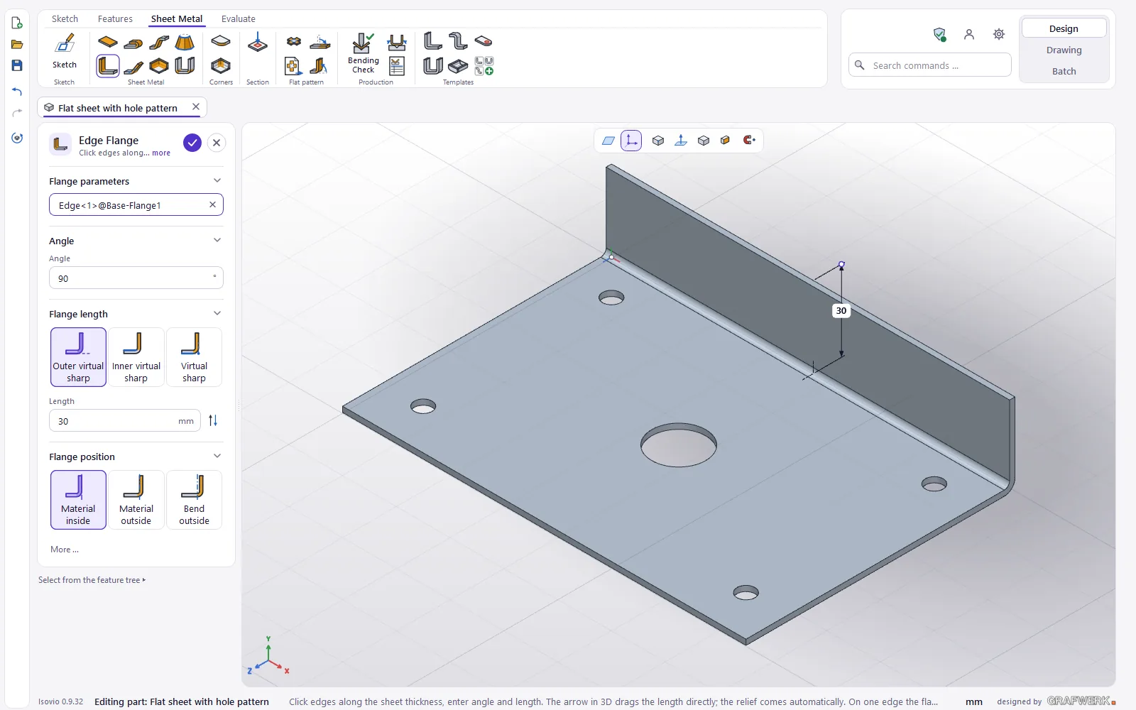
With exactly one edge you draw the flange profile as a rectangle or as a shape from a sketch. For the corners there are «Corner type» (butt, closed, gap, overlap, underlap) and «Corner relief» (as sheet metal parameters, none, tear, rectangular, round). If the flange is narrower than the edge, choose the «Bend relief»: rectangular, slot, tear or none, with width and depth across the bend zone. The flanges of one command form a group in the tree and can be edited together.
More commands: «Hem» (closed, open, tear drop, rolled), «Sketched Bend», «Jog», «Miter Flange», «Lofted Bend» (two sketches on two planes, bent or formed), «Convert to Sheet Metal», «Break Corner», «Close Corner» and «Normal Cut».
Flat pattern
«Flatten» switches between the folded and the flat part. Bend lines up are blue, down orange, each with angle and radius; the blank size is shown in the status line.
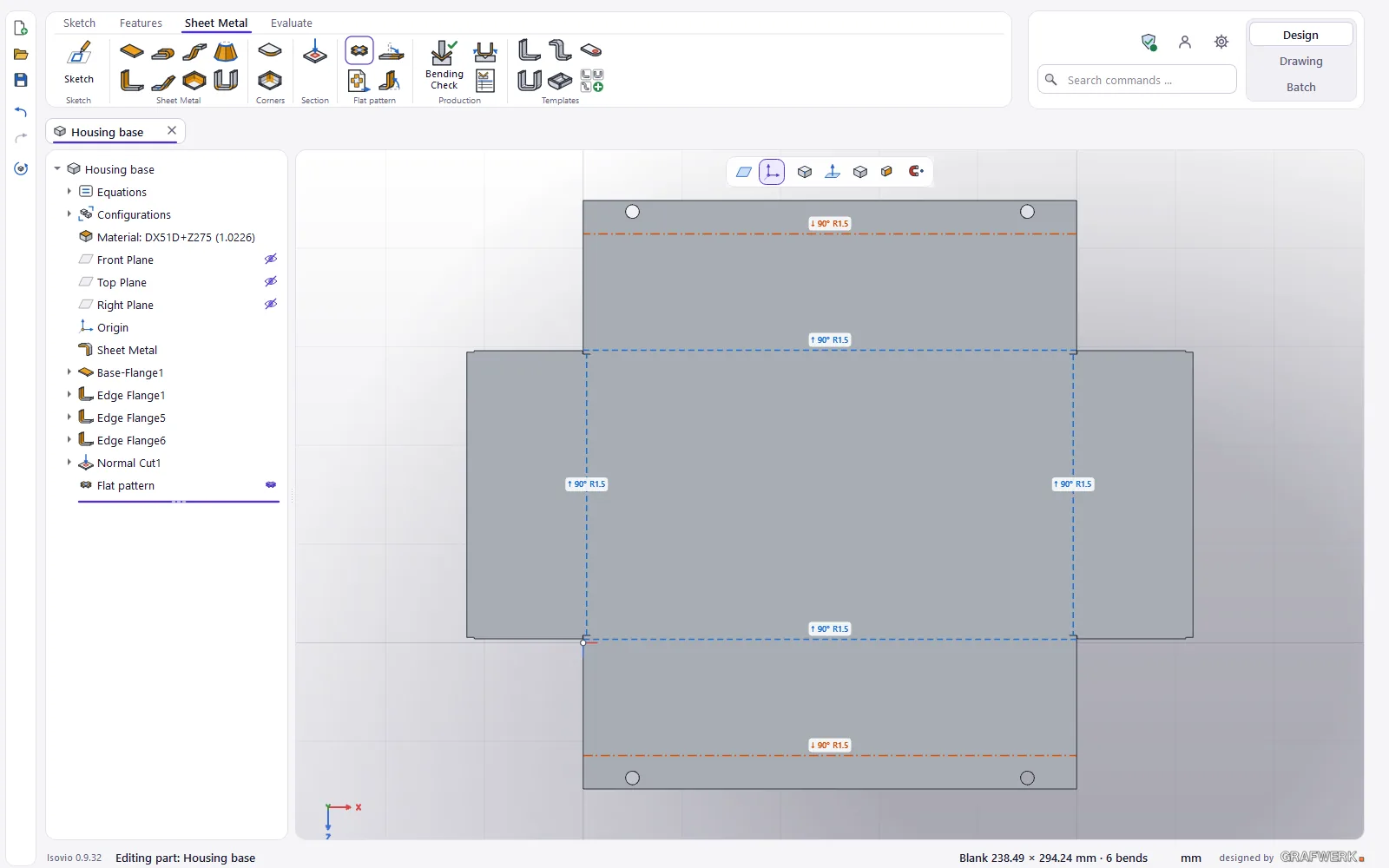
«Flat pattern as DXF» writes the flat pattern at 1:1 with the layers KONTUR, BIEGELINIE_AUF, BIEGELINIE_AB and TEXT, ready for cutting. For cuts across the bend zone there are «Unfold» and «Fold».
Bending check
Sheet Metal › Production › «Bending Check» (sheet metal parts only) checks every bend on the chosen press brake.
- At the top choose the machine and the tool set: automatic, straight punch only, gooseneck only or radius punches first.
- Every bend has a card with a traffic light (OK, note, problem), a choice of die and punch, and rᵢ/b_min, force, utilisation and overbend. A click on a card shows the bend in 3D.
- ✓ saves the result in the part. From then on the status line shows the state of the bending check: ok, notes, errors or out of date.
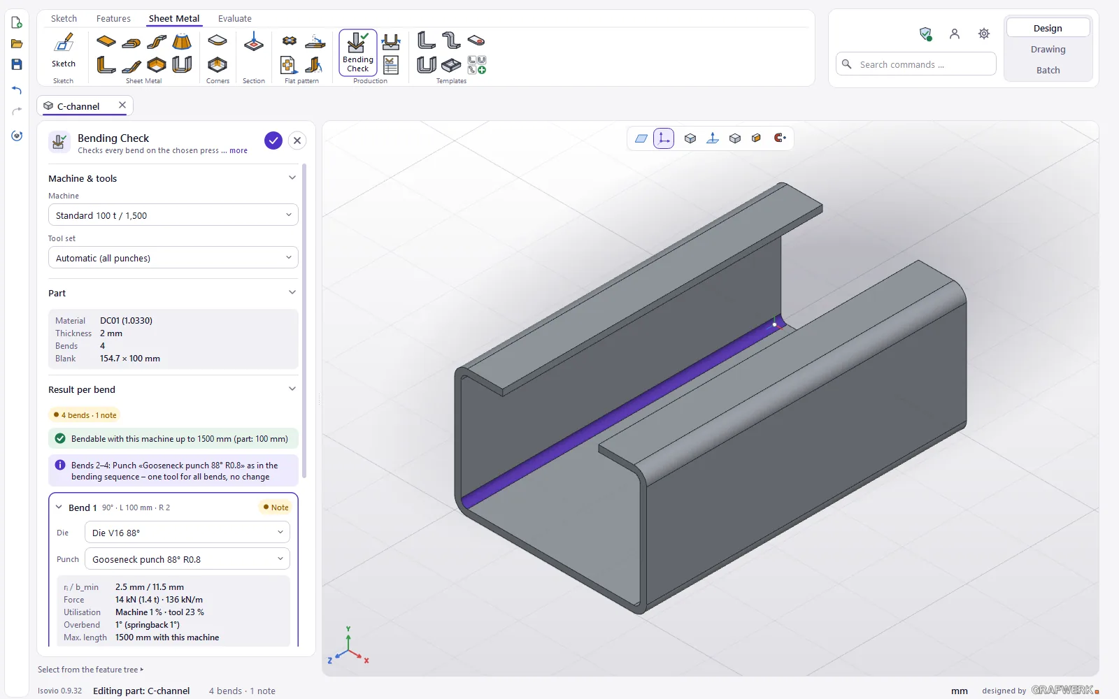
In the panel, «Radius übernehmen» takes the radius of the die into the sheet metal parameters, so that the flat pattern matches the press brake. Beside it are «Bending sequence …», «Tools & machines …» and «▶ Simulate».
Tip The values of the bending check are guide values, not an approval.
Bending sequence and simulation
«Bending Sequence» looks for a sequence without collisions and shows the cross section step by step: punch, die, back gauge, turning over and collisions in red. You can choose the best sequence, alternatives or your own order, whose steps you drag; every change is checked again at once. «Save setup sheet …» writes a PDF with the part, the check result, the tool setup and the sequence.
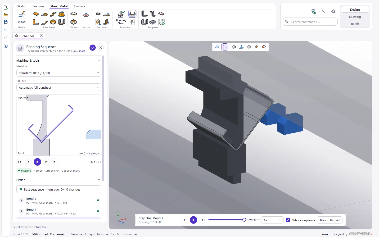
At the same time the 3D simulation runs: for every bend the punch moves down, bends, the sheet springs back, the punch moves up. The bar at the bottom offers previous and next bend, play, a slider, speed 0.5 to 4×, «Whole sequence» and «Back to the part». In a collision part and tool turn red. Simulate a single bend with «▶ Simulate» in the bending check.
Manage tools and machines under «Bending Tools & Machines …» (command search, button in the bending check or Settings › Design › Bending). Built in are a straight punch and a gooseneck 88° R0.8, radius punches R2 to R10, dies V6 to V24 with 88° and the machine «Standard 100 t / 1,500». Create your own tools with «New …», also from a DXF file or from a folder of DXF files.
Assemblies
An assembly has the tabs Assembly, Standard Parts and Evaluate. Parts are inserted and mated and can then be moved live, as far as the mates allow.
Creating an assembly and inserting parts
Create an empty assembly with menu «New» › «New assembly» or with the button on the start page. «Make Assembly from Part» turns an open part into an assembly containing it, fixed at the origin.
- «Insert Component»: choose an open document, or an Isovio part, an assembly or a STEP file with «Browse …».
- The part hangs transparent at the mouse pointer. A click puts it down, with its underside on a planar face, otherwise on the floor.
- Under «More …», «Qty» places a copy with every click and «Place at the origin» puts the part on the origin. ✓ ends; without a click the first part is fixed at the origin.
Dragging with the left mouse button moves a part along its remaining free movements; Alt + right mouse button turns it (with the preset «SolidWorks» the right button alone). Fix and float with «Fix/Float», with the pin icon in the tree row or with the right click.
Mates
- Choose Assembly › «Mate», or right click a face or edge of a part.
- Under «Mate selections» choose two elements with Ctrl + click: faces, edges, vertices, planes or axes. Only the mates that fit them appear.
- Choose the type: Coincident, Parallel, Perpendicular, Concentric, Distance, Angle, Tangent or Lock, and the «Alignment» (Aligned or Anti-aligned). Isovio suggests alignment and value, the part jumps into place at once. Accept with ✓.
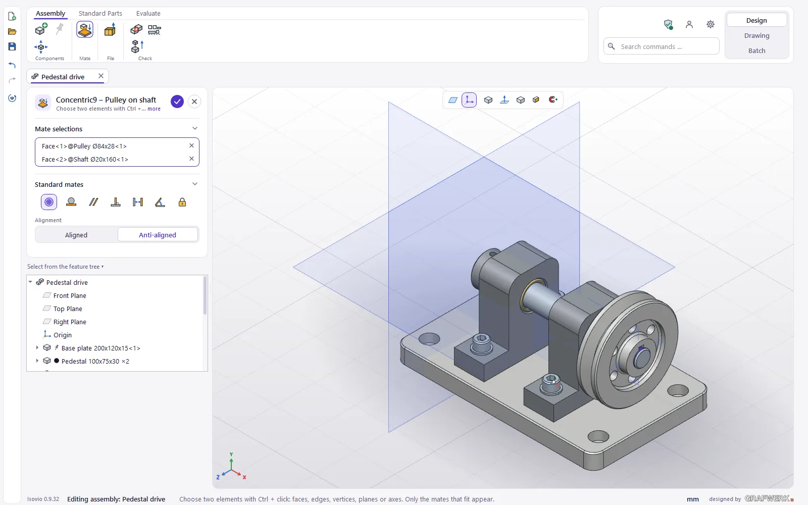
Every mate is listed under both parts and in the folder «Mates». A double click opens «Edit mate», the right click offers suppress and delete. The tree marks contradictions red or yellow, the tooltip says why.
Insert sub-assemblies like parts. With a right click › «Rigid» a sub-assembly moves as one body, with «Flexible» according to its own mates.
Standard parts
The «Standard Parts» tab brings screws, nuts and washers, bearings, pins and keys as well as weld and press-in elements into the assembly. «Insert Standard Part …» opens the standard parts library with categories, standards and a search, for example for «912 M8», «6204» or «key». Every tile in the ribbon opens the panel directly.
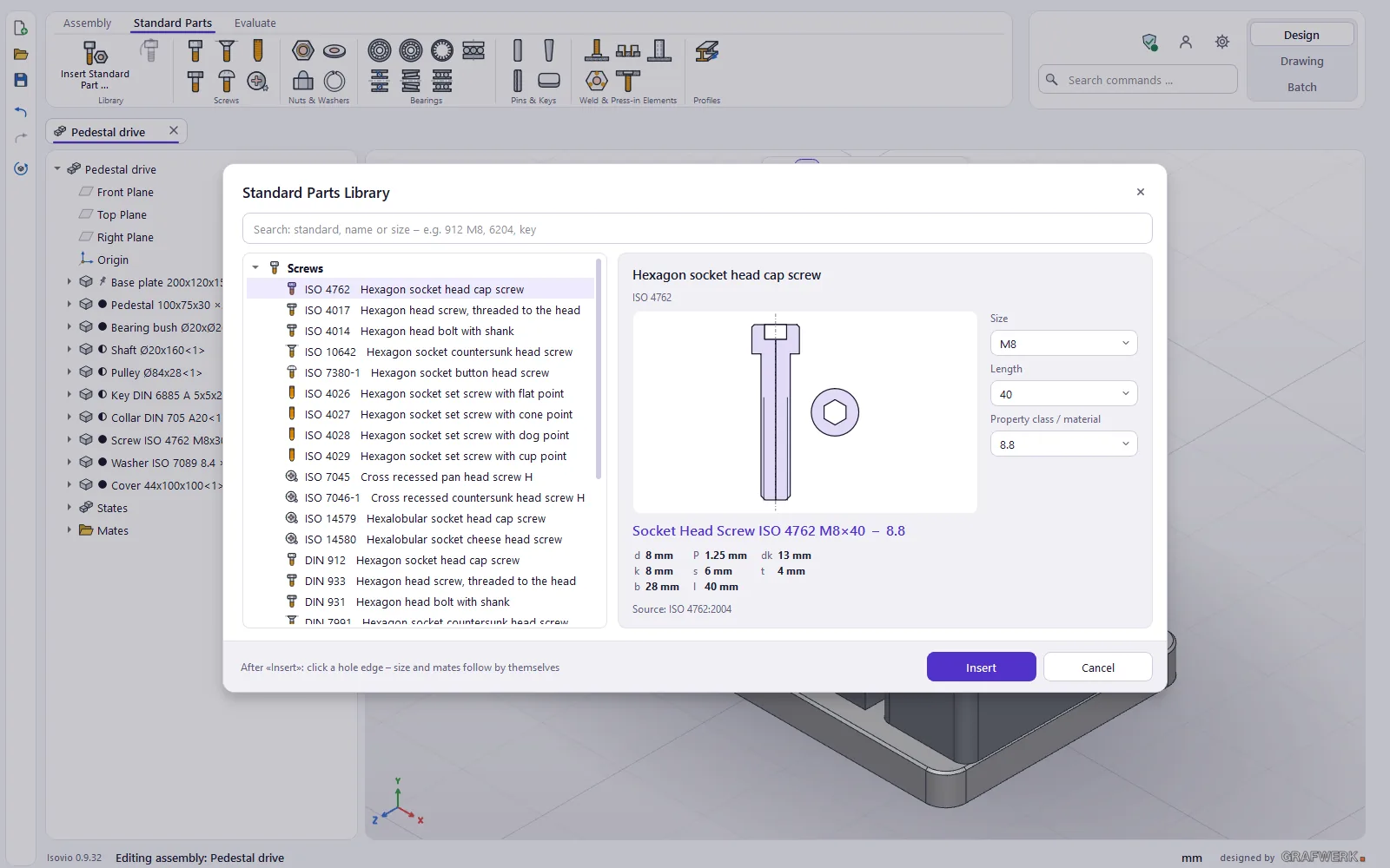
- In the panel «Insert Standard Part» choose category, standard, size, length and property class, or leave «Fit the size to the hole» and «Length from the hole depth» switched on.
- Click a hole edge, a shaft end or a face: the part sits there, mated concentric and coincident. Every further click places another one; ✓ or Esc ends.
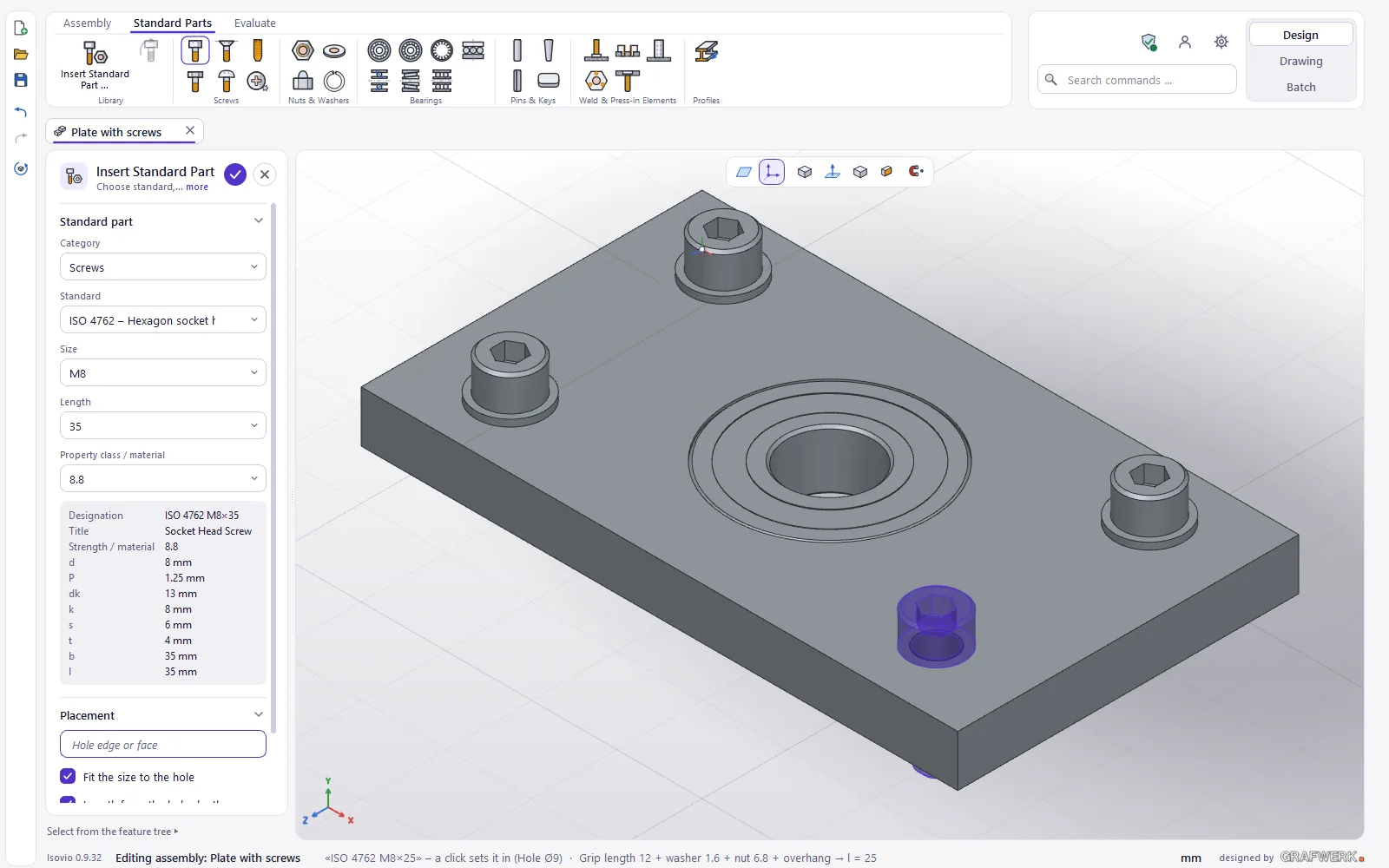
Isovio calculates the screw length from the grip length and the engagement depth (steel 1·d, cast iron 1.25·d, aluminium 2·d), for a through bolt with washer, nut and overhang, and takes the next standard length; the calculation is shown in the status line. «Change Standard Part» swaps size, length, standard or class, the mates stay.
Exploded view and states
Assembly › Check › «Exploded View»: the components move apart animated, parts on a common axis only along that axis. The panel offers «Distance (%)», «Explode lines», «Show axes» and «Take sub-assemblies apart»; ✓ keeps the explosion, ✗ takes it back. Fixed parts stay where they are.
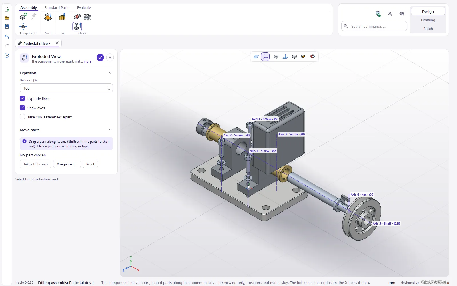
By hand: dragging a part moves it along its axis, with Shift the parts further out move along. The panel has «Take off the axis», «Assign axis …» and «Reset».
The explosion is saved as the state «Explosion 1». The tree folder «States» holds the base state «Assembled»; a right click on the folder creates «New state», «New explosion» or «New flat lay», a double click activates a state. A mate can apply «Only in this state», distances and angles can have their own value per state.
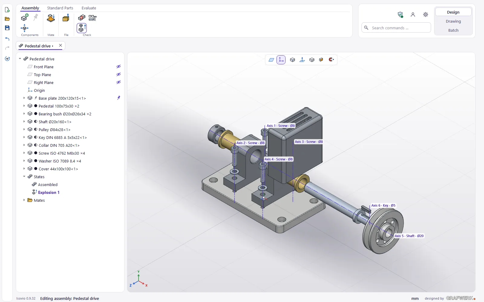
Tip On the drawing you choose the state per view: click the view, then «State» and «Explode lines» in the panel.
Flat lay
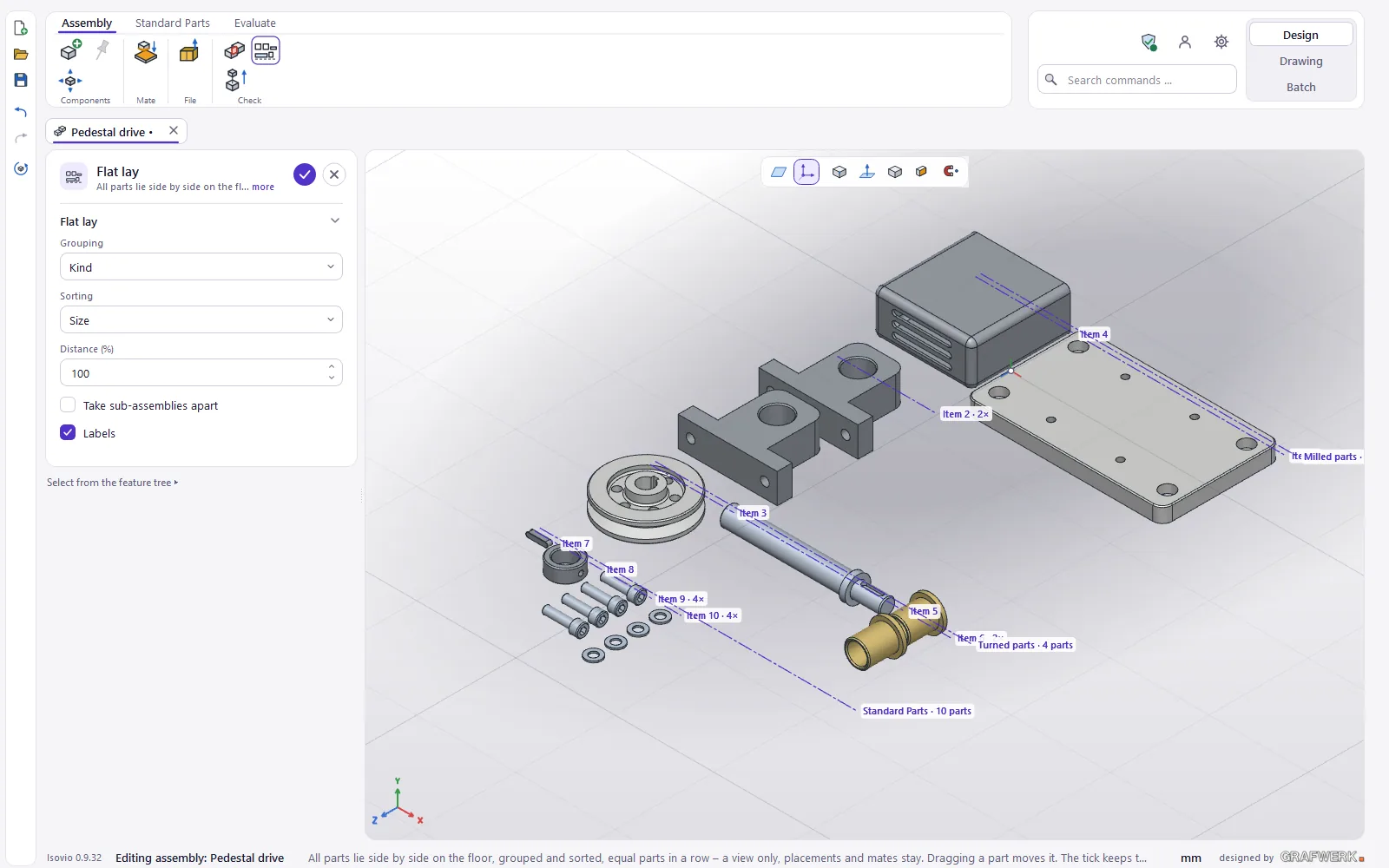
Assembly › Check › «Flat lay» lays all parts side by side on the floor, each on its largest face. The panel offers «Grouping» (kind, material or none), «Sorting» (size or position), «Distance (%)», «Take sub-assemblies apart» and «Labels» with «Pos. n · k×». It is saved as the state «Flat lay 1», also for drawing views.
Bill of materials and more
Right click the top row of the tree › «Bill of materials …»: the «Indented bill of materials» shows every sub-assembly with its parts indented, the «Quantity bill of materials» every part once with its total. «Save as CSV …» saves the tab shown, a double click on a row selects the parts in 3D.
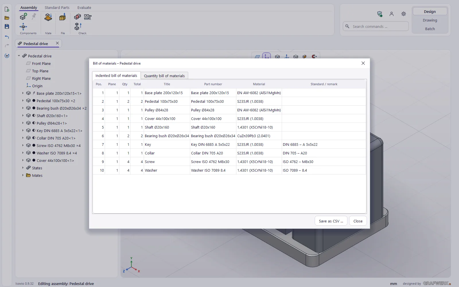
- «Interference Detection»: chosen or all components; a click in the result list shows the overlap in red.
- «Section view» with «Exclude from section», for example for screws and shafts.
- «Pack and Go»: the assembly with all its parts into a folder or a ZIP file.
- «Create drawing» makes the assembly drawing with item numbers and parts list, «Draw individual parts» one drawing per part; standard parts are skipped.
- «Export»: STEP, IGES, STL, 3MF, OBJ and glTF.
Drawing
The Drawing area holds the editor. This is where every drawing gets finished, whether it comes from Design, from a STEP file or from the automatic mode.
Creating a drawing
In Design choose Evaluate › «Create drawing»: the drawing opens as a tab in the editor, the part is saved first if needed. The drawing knows threads, fits and material from the model.
With nothing open, the editor shows «Start a drawing» with four tiles: «Drawing from a part in Design», «Drawing from STEP», «Open drawing (.fdw)» and «Batch (automatic mode)». If you drag in several models, Isovio asks: a batch in the automatic mode or one by one in the editor.
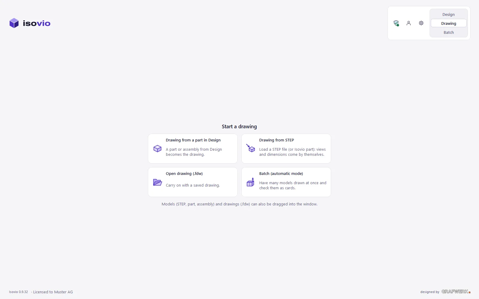
The editor
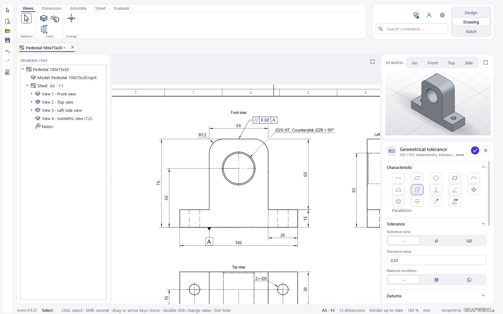
At the top the tabs Views, Dimension, Annotate, Sheet and Evaluate, on the left the drawing tree, in the middle the sheet. On the right a small 3D view (Iso, Front, Top, Side, «Full screen») above the panel. The panel belongs to the selection and works live; ✓ ends, ✗ takes back. With nothing selected it shows the sheet with size and scale.
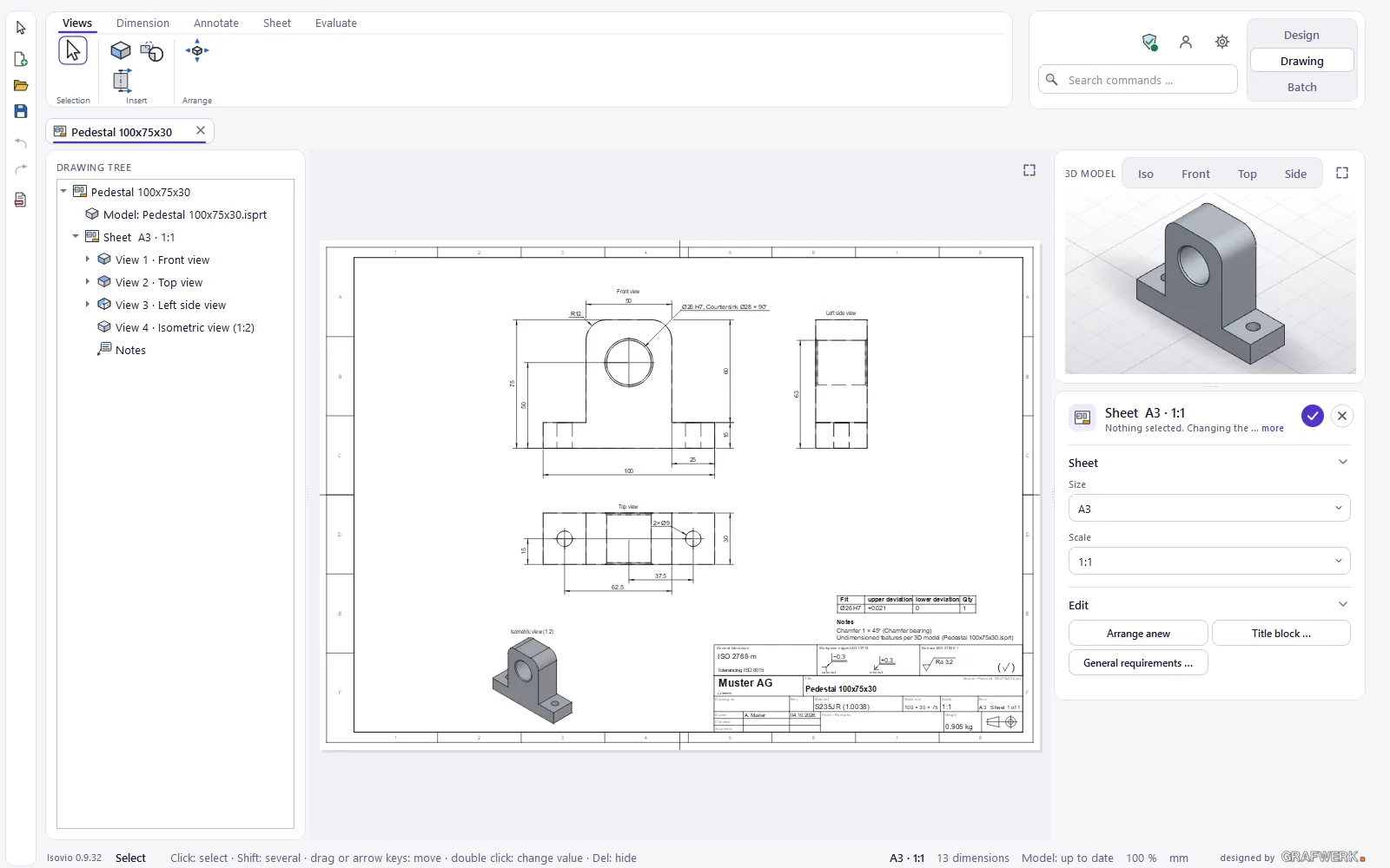
The drawing tree lists model, sheet and views with their dimensions, symbols and notes. The eye hides and shows, F2 renames a view. Objects whose edge no longer exists after a change of the model end up under «Nicht zugeordnet» (unassigned): drag the dimension line onto an element or delete it.
- «Add view»: front, top, left, right, bottom or back.
- «Section»: click two points of the cutting line, then the viewing direction.
- «Detail»: click the centre, then the radius.
- «Arrange anew» arranges the views again; Sheet › «Format / scale» chooses A4 to A0.
Dimensions and fits
The «Dimension» tab has length, aligned, diameter, radius and angle; the tools snap to corners, edge midpoints and circle centres.
- Click a dimension: the «Dimension» panel opens on the right.
- Under «Value» you find value or text, «Prefix» (Ø, R, M, 2×) and «Suffix».
- Under «Tolerance» choose None, ±, Deviations or Fit. For a fit to ISO 286, such as H7 or g6, Isovio works out the deviations itself.
- Under «Kind» you make an auxiliary dimension (in brackets) or a theoretically exact dimension (framed).
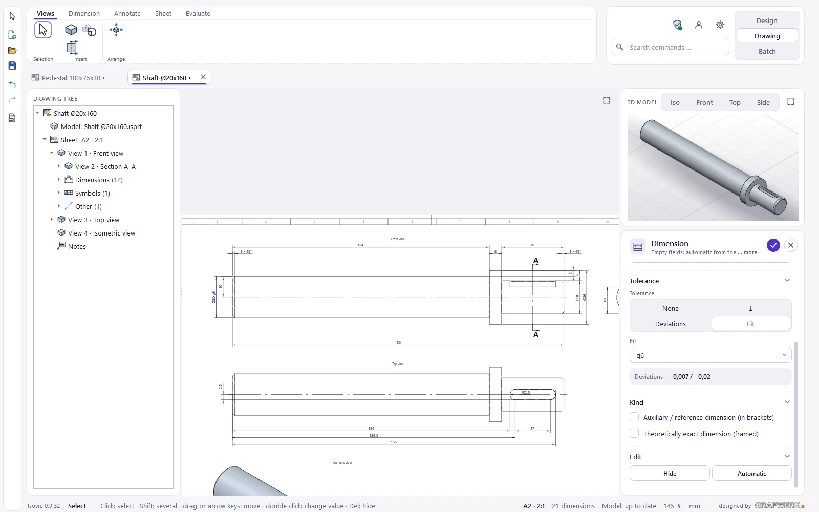
Tip A double click on a value changes it right on the sheet. Select several dimensions with Shift + click; the panel then offers «Align» and «Stack evenly».
Geometrical tolerances, datums, roughness
The «Annotate» tab places geometrical tolerances to ISO 1101, datums to ISO 5459, roughness to ISO 21920-1 and notes.
The «Geometrical tolerance» panel has 14 characteristics, the tolerance zone (Ø or SØ), the material condition (Ⓜ, Ⓛ), up to three datums as well as Ⓟ, Ⓕ, CZ and the composite frame. Roughness knows material removal required, any process and not permitted, all around and the fields a to e.
Title block and general requirements
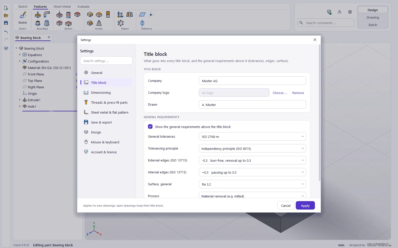
A double click on the title block opens its panel: title, drawing no., revision, material, surface, drawn, checked and approved with dates; a double click into an empty date sets today. In the revision table, the button for a new revision suggests index, date and name; a click on the index header switches between 1·2·3 and A·B·C.
Above the title block sits the block of general requirements. A click into a cell opens general tolerances (ISO 2768, ISO 22081), tolerancing principle (ISO 8015), outer and inner edges (ISO 13715) and surface; «Save as default for new drawings» keeps the values.
Saving, export and keeping in step with the model
- Drawings are saved as Isovio drawings (.fdw). «Save as …» offers «Isovio drawing (editable)» or «PDF with drawing data»; the editor opens such a PDF again.
- Evaluate: «Export as PDF» (Ctrl+P), «Export as …» (Ctrl+Shift+E: DXF with layers, SVG, PNG), «Export all …» and «Print».
- Isovio checks the model every second: a part saved anew is read again, your changes to the drawing stay.
- Every two minutes a backup «Name.fdw~» is written. After a crash Isovio offers the recovery when you open the drawing.
- Drawings in inches: Settings › «Dimensioning» › «Dimension drawings in». Threads, fits and ISO 2768 stay metric.
Batch: the automatic mode
The automatic mode (the Batch area) draws STEP models from other CAD systems by itself, even hundreds at once. You check what needs a look and save them all as Isovio drawings.
Adding models
- Drag STEP files or whole folders into the window («Release to draw»). For a folder Isovio also offers «Use as output folder».
- Or click the tile «Drag STEP models here» or press Ctrl+O and choose files.
- Isovio reads and draws in the background; every file becomes a card.
If a part of the same name is already on the board, «Part already open» asks: Read again, Replace, Keep both or Skip.
The board
The list «Models» sorts the cards into the sections «Check», «Ready», «In progress» and «Saved»; a click on the head folds a section. A card shows the sheet, the name, an info line (e.g. «Bent part · 2 mm · 3 bends»), size and scale and the icons «Save» and «Open in the editor». Sheet metal parts carry a bending light at the top left: «Bendable» or «check».
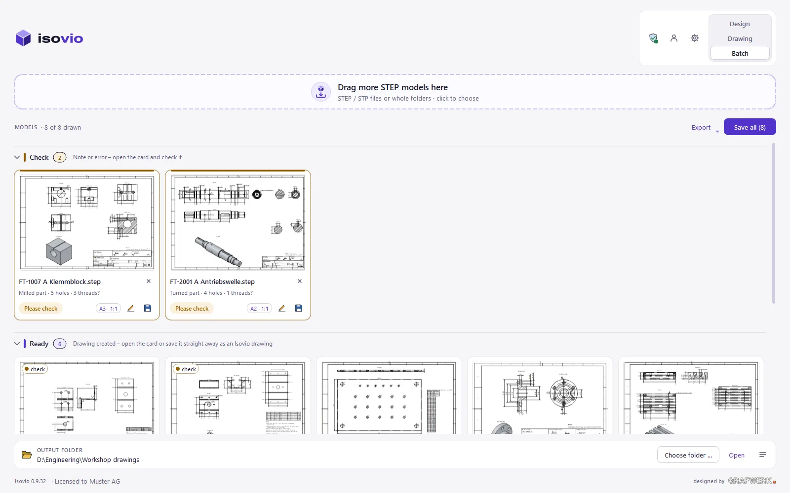
The right click on a card offers among others «Edit in the editor», «Save», «Export as PDF», «Export as …», «Show in folder» and «Align view …». A card can be dragged into the Explorer: a PDF is created.
Checking a card
A click on a card opens the detail view: on the left the large sheet (the mouse wheel zooms, dragging pans, a double click shows the whole sheet), on the right the 3D model and the settings of the drawing.
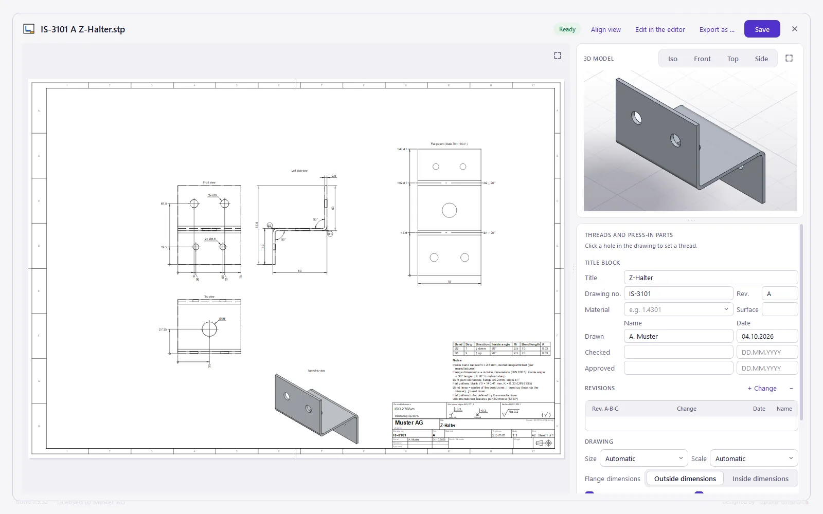
- Click a hole on the sheet: choose threads and press-in parts, «Fit / tolerance» to ISO 286 or «Only this one hole».
- «Threads and press-in parts»: confirm suggestions one by one or «Accept all suggestions».
- «Title block»: title, drawing no., revision, material, surface and names with dates.
- «Drawing»: size (automatic, A4, A3, A2 landscape), scale, flange dimensions outside or inside, plus hole positions, general requirements, flat pattern, hidden edges, break long parts and grid reference border.
- At the top: «Align view», «Edit in the editor», «Export as …» and «Save».
«Align view» turns the part on the sheet: arrow keys by 90°, PgUp/Q and PgDn/E in the front view; «Free rotation» with mouse and arrow keys (15°, with Shift 1°). Enter or «Apply» confirms, «Automatic orientation» resets.
Saving and exporting
«Save all» stores an Isovio drawing (.fdw) for every finished card in the output folder. With the option «Save drawings and PDFs next to the STEP file» switched on under Settings › «Save & export», they go next to the model.
The bar at the bottom shows the output folder with «Choose folder …» and «Open»; the default is «Documents\Werkstattzeichnungen».
«Export ▾» turns all finished drawings into PDF («Export all as PDF», in the background; a second click stops it) or DXF, SVG, PNG and PDF («Export all as …»). «Remove saved» takes the saved cards off the board.
Tip How many models are computed at the same time and how long one may take is set under Settings › «General» › «Computing».
Settings and shortcuts
The gear at the top right opens the settings. On the left are the pages and the search «Search settings …», at the bottom «Cancel» and «Apply».
The pages of the settings
| Page | What you find there |
|---|---|
| General | Language, colour scheme, background of the 3D views, units, computing, updates |
| Title block | Company, company logo, drawn by; general requirements with general tolerances, tolerancing principle, edges and surface |
| Dimensioning | Decimal sign, dimension drawings in, flange dimensions, holes; sheet and views with projection method, size, scale, hidden edges and grid reference border |
| Threads & press-fit parts | Remembered decisions and how to forget them |
| Sheet metal & flat pattern | Flat pattern on the drawing, K-factor table, tolerances for bent parts |
| Save & export | Output folder, saving next to the STEP file, open the exported PDF, library folder |
| Design | Snapping while sketching, save automatically, show threads in 3D, bending with default machine and tool set |
| Mouse & keyboard | Mouse preset, help popups, keyboard shortcuts |
| Account & licence | Licence overview, open account & licence, third-party licences |
Mouse
| Action | Isovio (default) | SolidWorks |
|---|---|---|
| Rotate view | hold the right button, the middle one works too | middle button |
| Pan view | Ctrl + right button | Ctrl + middle button |
| Zoom | Shift + right button or mouse wheel | Shift + middle button or mouse wheel |
| Rotate component | Alt + right button on the part | right button on the part |
A short right click without moving always opens the context menu; a double click with the middle button zooms to fit. Choose the preset and every button on its own under Settings › «Mouse & keyboard»; a right click into the empty 3D view leads there directly with «Mouse & keyboard …».
On the sheet (Batch and editor) the mouse wheel zooms, dragging on empty paper pans. In the editor the middle button always pans, Shift + click selects several objects, Shift + drag draws a selection frame.
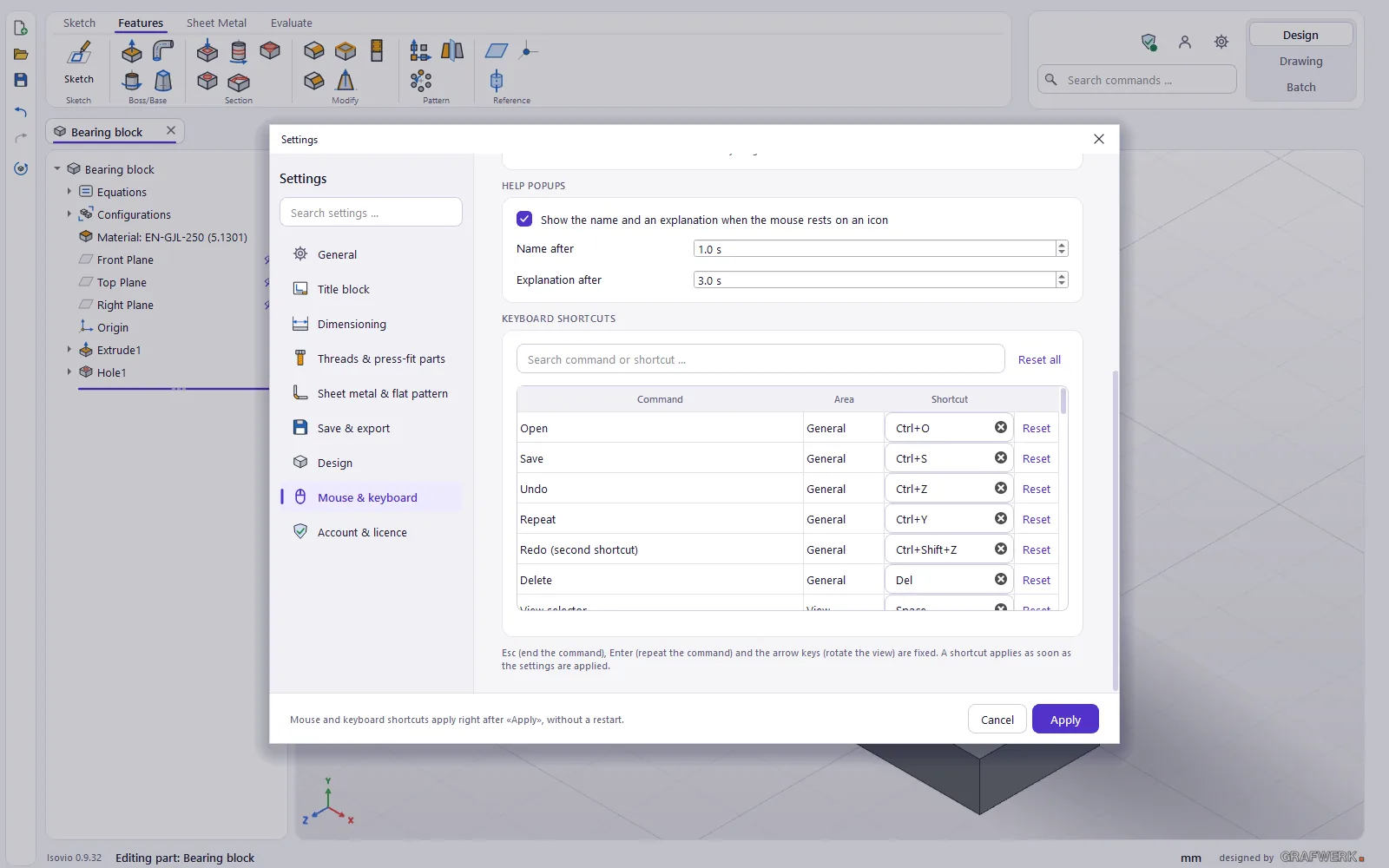
Keyboard shortcuts
Every default shortcut can be changed under «Mouse & keyboard»; the table shows shortcuts used twice in red.
| Ctrl+O | Open |
| Ctrl+S | Save |
| Ctrl+Shift+S | Save as … |
| Ctrl+Z | Undo |
| Ctrl+Y / Ctrl+Shift+Z | Repeat |
| Del | Delete |
| Ctrl+N | New Part |
| Ctrl+B | Rebuild |
| Ctrl+M | Measure |
| Ctrl+1 … Ctrl+6 | View front, back, left, right, top, bottom |
| Ctrl+I / Ctrl+7 | Isometric |
| Ctrl+8 | Normal To |
| F | Zoom to fit |
| Space | View selector |
| Alt+↑ / Alt+↓ | Move a feature in the tree |
| H / V | Sketch: horizontal / vertical |
| ↑ ↓ ← → | Turn the view by 15°, with Shift by 90° |
| Alt+← / Alt+→ | Turn about the viewing axis |
| Enter | Confirm the panel or repeat the last command |
| Esc | End command, tool and selection |
| ↑ / ↓ | In value fields ±1, with Shift ±10 |
| Ctrl+P | Export as PDF |
| Ctrl+Shift+E | Export as … |
| ↑ ↓ ← → | Move the selection by 0.5 mm, with Shift 5 mm |
| F2 | Rename view |
| Esc | Step by step: tool, selection, large view |
| Enter | Start the best match |
| Esc | Clear the field |
Account and licence
The person icon at the top right opens «Account & licence»: company, scope, seats, valid until and this PC, plus «Update licence», «Change password …» and «Sign out and free seat». When you change PCs, free the seat here. The shield with the coloured dot beside it shows the licence status; a click opens the overview with «Check now».
Isovio Draw contains the Drawing and Batch areas; Design is an add-on, the Complete bundle contains both. More under pricing.
This guide describes Isovio 0.9.32. We are happy to answer questions through the contact form; frequent questions are in the FAQ.
Try Isovio on one of your own parts.
Free for 30 days, all three areas including Design, no credit card.